

Shinkawa CMU-15A (CMU15A) Industrial Camera Controller
Shinkawa CMU-15A (CMU15A) Industrial Camera Controller is an advanced image processing and vision interface unit manufactured by Shinkawa Electric. Specifically engineered for automated semiconductor packaging machinery, high-speed wire bonders, and microelectronic pick-and-place systems, the CMU-15A coordinates high-resolution optical image capture, pattern recognition logic, and precise hardware strobe synchronization to enable exact alignment of silicon dies and fine-pitch leads.
Technical Table
| Specification Parameter | Value / Details |
| Model Code | CMU-15A (CMU15A) |
| Manufacturer | Shinkawa Electric Co., Ltd. |
| Device Type | Industrial Camera Controller / Vision Interface Processing Unit |
| Input Channels | Multi-channel high-speed industrial camera inputs |
| Operating Voltage | +24V DC (±10%) auxiliary supply |
| Trigger Mechanism | Sub-microsecond hardware strobe and external motion sync triggering |
| Communication Protocols | Dedicated high-speed camera interface, RS-422/RS-485, system bus |
| Status Indicators | Panel Diagnostic LEDs (POWER, RUN, CAMERA LINK, FAULT) |
| Mounting Style | Rack mount / Internal electrical enclosure baseplate mounting |
Environmental Tolerance Conditions
Operating Temperature: 0°C to +50°C (32°F to 122°F)
Storage Temperature: -20°C to +70°C (-4°F to 158°F)
Relative Humidity: 10% to 90% RH (non-condensing)
Vibration Immunity: Conforms to IEC 60068-2-6 standard for semiconductor manufacturing machinery
Shock Resistance: 15g peak acceleration (IEC 60068-2-27)
Protection Class: IP20 (Designed for mounting inside cleanroom IP54/NEMA 12 control cabinets)
Operating Instructions
Pre-Installation Safety: Isolate main equipment power before installing or removing the CMU-15A controller.
Mounting: Secure the module to the machine’s electrical mounting plate using M4/M5 hardware with split lock washers to withstand rapid X-Y stage accelerations.
Vision Cabling: Connect industrial camera lines using double-shielded, high-flex camera cables. Secure strain-relief clamps near the connectors.
Grounding: Fasten a low-impedance ground strap from the chassis frame ground terminal to the equipment earthing bar to suppress electromagnetic interference (EMI).
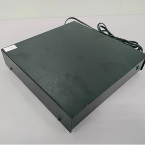
CMU-15A
System Parameter Configuration: Set exposure times, frame rates, and strobe delay values through the host equipment control software before initiating automated production runs.
Fault Diagnosis & Troubleshooting
POWER LED Off: Check the external +24V DC auxiliary power supply, terminal wiring connections, and internal protection fuses.
CAMERA LINK LED Inactive / Flashing: Inspect camera interface cables for damage or loose locking screws; verify camera power supply lines.
Alignment / Image Frame Errors: Clean camera lenses and optical light rings; check for dirty or obstructed optical pathways; verify external hardware strobe trigger signals.
FAULT LED Solid Red: Indicates a processor or vision board hardware error. Power cycle the system; if the error persists, board repair or replacement is required.
Related Models of the Same Series
CMU-13A (CMU13A): Vision camera processing controller variant
CMU-10 / CMU-12: Legacy industrial camera controller modules
EFU-10: Electronic Flame Off (EFO) spark generator unit for wire bonders
UTC-1000 (ZUP-02C): Universal system processing and communication motherboard
Storage Conditions
Storage Environment: Store indoors in a dust-free, cleanroom-compatible facility away from direct sunlight, moisture, and corrosive gas fumes.
Humidity Control: Keep relative humidity under 90% non-condensing.
Static Protection: Keep the module sealed in its anti-static ESD shielding bag until final installation on the equipment frame.