

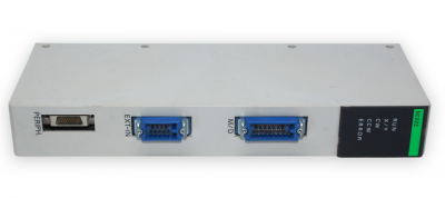
OMRON C500-NC222-E PLC
OMRON C500-NC222-E PLC
Memory Packs
The Memory Pack fits into the slot located on the left side of the CPU. Be
cause the Memory Pack is not provided with the PC upon delivery, a Memory
Pack must be selected and installed in the CPU. There are two Memory
Packs available, either RAM or ROM, that can be used in the C500H PC.
RAM Pack
Data can be randomly written to and read from the RAM Pack, making it pos
sible to enter your own program into the CPU. However, because this is not a
fixed program, the memory of the RAM Pack is erased when power is not
supplied to the CPU or when the RAM Pack is removed from the CPU.
Two models of RAM Packs are available, which vary in memory capacity:
16K, and 24K words. Refer to Appendix C Standard Models for model num
bers.
Using a Programming Console, execute FUN (01) and a search operation to
check the amount of memory available
Data contained in the ROM Pack is stored on EPROM chips and cannot be
altered or erased during the CPU’s operation. Write the user’s program to the
EPROM chips and mount the chips (3 max.) on the ROM chip. The entire
pack is installed in the CPU. Once the data is written to the chip the data will
not be lost when the power to the PC is OFF
When we speak of a PC, we usually think of it as a single object. But actually
even the simplest PCs are usually composed of several different devices. In
fact a single PC can be physically spread throughout a building, but we still
call it one PC.
In this section, we will start with a Backplane and use all the Units discussed
in Section 2 Description of All Components to build a PC.
There is no single Unit that can be said to constitute a Rack PC. To build a
Rack PC, we start with a Backplane. The Backplane for the C500 is shown
below.
C500-NC222-E
The Backplane is a simple device having two functions. The first is to provide
physical support for the Units to be mounted to it. The second is to provide
the connectors and electrical pathways necessary for connecting the Units
mounted to it.
The first device we will add to the Backplane is a Power Supply. The Power
Supply fits into the rightmost position on the Backplane and provides electric
ity at the voltages required by the other Units of the PC. It can also be used
to power devices other than the PC if necessary.
Power Supply
The core of the PC is the CPU. The CPU contains the program consisting of
the series of steps necessary for the control task. The CPU fits into the posi
tion directly to the left of the Power Supply
Unlike the CPU of the Package-type PC, the CPU of the Rack PC has no I/O
points built in. So, in order to complete this kind of PC we need to mount one
or more I/O Units to the Backplane. Mount the I/O Units to the Backplane by
pressing the I/O Unit firmly into position, making sure the connectors are
properly mated. Secure the Unit by tightening the mounting screws located
on the top and bottom of the Unit
I/O Units are where the control connections are made from the PC to all the
various input devices and output devices. As you can see from the figure,
there is still some space available on the right side of the Backplane. This
space is for any additional I/O Units that may be required
The figure above shows a total of eight I/O Units mounted to the Backplane.
Backplanes are available in different lengths, and can hold a different number
of I/O Units accordingly. Of course, not all I/O Units look exactly alike, but the
ones in the figure show their typical appearance. This configuration of Back
plane, Power Supply, CPU, and I/O Units is called a CPU Rack. This term
refers to the Backplane and all the Units mounted to it. However, if we want
to include more than eight I/O Units in our configuration we can add an addi