

OMRON C200H-RT201 PROGRAMMABLE CONTROLLER
OMRON C200H-RT201
High-density I/O Units are designed to provide high-density I/O capability and
include Group 2 High-density I/O Units and Special I/O High-density I/O Units.
Special I/O Units are dedicated Units that are designed to meet specific needs.
These include some of the High-density I/O Units, Position Control Units, High
speed Counter Units, and Analog I/O Units.
Link Units are used to create Link Systems that link more than one PC or link a
single PC to remote I/O points. Link Units include Remote I/O Units, PC Link
Units, Host Link Units, SYSMAC NET Link Units, and SYSMAC LINK Units.
SYSMAC NET Link and SYSMAC LINK Units can be used with the CPU11 only.
Other product groups include Programming Devices, Peripheral Devices,
and DIN Rail Products.
The following are the basic steps involved in programming and operating a
C200H. Assuming you have already purchased one or more of these PCs, you
must have a reasonable idea of the required information for steps one and two,
which are discussed briefly below. This manual is written to explain steps three
through six, eight, and nine. The relevant sections of this manual that provide
more information are listed with each of these steps.
1. 2. 3…
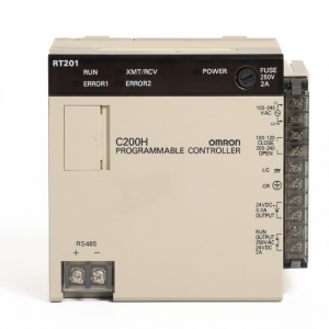
C200H-RT201
Control System Design
1. Determine what the controlled system must do, in what order, and at what
times.
2. Determine what Racks and what Units will be required. Refer to the C200H
Installation Guide. If a Link System is required, refer to the appropriate Sys
tem Manual.
3. On paper, assign all input and output devices to I/O points on Units and de
termine which I/O bits will be allocated to each. If the PC includes Special I/O
Units or Link Systems, refer to the individual Operation Manuals or System
Manuals for details on I/O bit allocation. (Section 3 Memory Areas)
4. Using relay ladder symbols, write a program that represents the sequence
of required operations and their inter-relationships. Be sure to also program
appropriate responses for all possible emergency situations. (Section 4
Writing ana Inputting the Program, Section 5 Instruction Set, Section 6 Pro
gram Execution Timing)
5. Input the program and all required operating parameters into the PC. (Sec
tion 4-7 Inputting, Modifying, and Checking the Program.)
6. Debug the program, first to eliminate any syntax errors, and then to find ex
ecution errors. (Section 4-7 Inputting, Modifying, and Checking the Pro
gram, Section 7 Program Monitoring and Execution, and Section 8
Troubleshooting)
7. Wire the PC to the controlled system. This step can actually be started as
soon as step 3 has been completed. Refer to the C200H Installation Guide
and to Operation Manuals and System Manuals for details on individual
Units.
8. Test the program in an actual control situation and carry out fine tuning as
required. (Section 7 Program Monitoring and Execution and Section 8
Troubleshooting)
9. Record two copies of the finished program on masters and store them safely
in different locations. (Section 4-7 Inputting, Modifying, and Checking the
Program)
Designing the Control System is the first step in automating any process. A PC
can be programmed and operated only after the overall Control System is fully
understood. Designing the Control System requires, first of all, a thorough un
derstanding of the system that is to be controlled. The first step in designing a
Control System is thus determining the requirements of the controlled system
The first thing that must be assessed is the number of input and output points
that the controlled system will require. This is done by identifying each device
that is to send an input signal to the PC or which is to receive an output signal
from the PC. Keep in mind that the number of I/O points available depends on
the configuration of the PC. Refer to 3-3 IR Area for details on I/O capacity and
the allocation of I/O bits to I/O points.
Next, determine the sequence in which control operations are to occur and the
relative timing of the operations. Identify the physical relationships between the
I/O devices as well as the kinds of responses that should occur between them.
For instance, a photoelectric switch might be functionally tied to a motor by way
of a counter within the PC. When the PC receives an input from a start switch, it
could start the motor. The PC could then stop the motor when the counter has
received a specified number of input signals from the photoelectric switch.
Each of the related tasks must be similarly determined, from the beginning of the
control operation to the end.