

OMRON CJ1W-NCF71 Position Control Units
OMRON CJ1W-NCF71
Introducing a Position Control Unit that can control up to 16 axes across
a MECHATROLINK-II* high-speed field network. With it, every aspect of multi-axis
systems from machine design to future expansions can be changed quickly and simply
OMRON has developed a whole new environment that
seamlessly integrates different control devices and
networks over the entire life cycle of equipment and
machines, ranging from design and startup to operation
and maintenance. The system will still be viable as new
systems are developed and new control devices and
controllers become available. It all begins with OMRON
Standard Libraries.
OMRON Standard Libraries are software applications that customers can
load into their system and use without modification. The OMRON FB
Library and Smart Active Parts (SAPs) Library are available now. These
libraries simplify the software developed for interface components
between Programmable Controllers (PLCs) or Programmable Terminals
and various other control devices. They also improve the quality of the
software by using standardized software components.
The OMRON FB Library contains functional components for
Programmable Controllers (PLCs). These components can be used by
customers to produce finished programs that interface with various
control devices in much less time. Since the components are
standardized, they also improve the quality of the finished programs.
The Smart Active Parts (SAPs) Library, formerly known as the Device
Library, consists of screens with functions for Programmable Terminals.
SAPs can be used on screens developed by customers to produce
finished screens that interface with various control devices in much less
time. Since the components are standardized, they also improve screen
quality.
J1W-NCF71
CPU Bus Unit
CJ Series
0 to F
Words allocated in CPU Bus Unit Area: 25 words (15 output words, 10 input words)
Allocated in one of the following areas (user-specified): CIO, Work, Auxiliary, Holding, DM, or EM Area
Number of words allocated: 50 words (25 output words, 25 input words) x Highest axis number used
Specification Item
Common Operating Memory Area
Axis Operating Memory Area
Compatible devices
Model
Unit classification
Applicable PLCs
Unit number settings
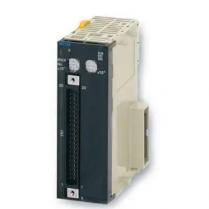
CJ1W-NCF71
allocations
Position commands
Speed commands for
position control
Servo lock/unlock
Position control
Establishing the origin
Jogging
Interrupt feeding
Speed control
Torque control
Stop functions
Acceleration/deceleration curves
Torque limit
Override
Servo parameter transfer
Monitoring function
Software limits
Backlash compensation
Position Control Unit
Servo Driver I/O
Self-diagnostic functions
Error detection functions
Internal current consumption
Dimensions
Weight
Ambient operating temperature
External I/O
Control
functions
Control
commands
Control method
Maximum number of controlled axes
Control commands executed using MECHATROLINK-II synchronous communications
16 axes–2.147.483.648 to 2.147.483.647 (command units) (The command unit depends on the Electronic Gear Settings in the Servo Parameter
Origin search: Establishes the origin using the specified search method.
Present position preset: Changes the present position to a specified position to establish the origin.
Origin return: Returns the axis from any position to the established origin.
Absolute encoder origin: Establishes the origin using a Servomotor that has an absolute encoder, without having to use an origin search.
Outputs pulses at a fixed speed in the CW or CCW direction.
Performs positioning by moving the axis a fixed amount when an external interrupt input is received while the axis is moving.
Performs speed control by sending a command to the Servo Driver speed loop.
Performs torque control by sending a command to the Servo Driver current loop.
Any of the following can be set: a trapezoidal (linear) curve, an exponential curve, or an S-curve (moving average).
Restricts the output torque during axis operation.
Multiplies the axis command speed by a specified ratio. Override: 0.01% to 327.67%
Reads and writes the Servo Driver parameters from the ladder program in the CPU Unit.
Monitors the control status of the Servo Driver, such as the command coordinate positions, feedback position, current speed, and torque.
Sets limits on the software level applied to the positioning range of axis operations.
Compensates for the amount of play in the mechanical system according to a set value.
One MECHATROLINK-II interface port
CW/CCW limit inputs, origin proximity inputs, external interrupt inputs 1 to 3 (can be used as external origin inputs)
Watchdog, flash memory check, memory corruption check
Overtravel, Servo Driver alarm detection, CPU error, MECHATROLINK communications error, Unit setting error
360 mA max. at 5 V DC
31 x 90 x 65 mm (W x H x D)
95 g max.
0 to 55°C
Deceleration stop: Decelerates the moving axis to a stop.
Emergency stop: Positions the moving axis for the number of pulses remainin