

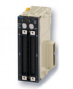
OMRON CJ1W-NC413 Position control unit
CJ1W-NC413
Position control unit, 4 axes, NPN open collector pulse string output, 500 KHz
Specifications
I/O system CJ I/O Bus
Expansion unit type Special I/O Unit
Type of module Positioning
Digital input type Line driver (RS-422), NPN, No voltage, PNP
Digital output type NPN, Open collector
Number of encoder input channels 0
Max. number of PTP axes 4
Number of pulse output channels 4
Max. pulse output frequency 500 kHz
I/O connection type FCN (plug not included)
Number of I/O connectors 2
Detachable I/O terminal block
Suitable for safety functions
Communication port(s) None
Product Height (unpacked) 90 mm
Product Width (unpacked) 31 mm
Product Depth (unpacked) 66.5 mm
Product Weight (unpacked) 150 g
Explanations of PLC Setup Settings
Basic I/O Unit Input
Response Time
IOM Hold Bit Status at
Startup
The input response time can be set for Basic I/O Units by Rack and Slot num
ber. Increasing this value reduces the effects of chattering and noise.
Decreasing this value allows reception of shorter input pulses, (but do not set
the ON response time or OFF response time to less than the cycle time).
Pulses shorter than the input
response time are not received.
Input such as a
proximity switch
Input bit
CJ1W-NC413
Input response time Input response time
The default setting for the input response time is 8 ms and the setting range is
0 to 32 ms. When the input response time is set to 0 ms, the only delay will be
the delays in the Unit’s internal elements. For information on the Unit’s internal
elements, refer to Appendix A Specifications of Basic I/O Units and check the
input response time for the Unit that you are using.
The input response time settings are transferred to the Basic I/O Units when
the PLC is turned ON.
When the Unit’s settings are changed, they are stored in A220 to A259 (Actual
Input Response Times for Basic I/O Units). When the settings in the PLC
Setup have been changed with the PLC in PROGRAM mode, the PLC Setup
settings will differ from the actual settings in the Units. In this case, the values
in A220 to A259 can be checked to see the input response times actually set
in the Units.
The IOM Hold Bit (A50012) can be turned ON to retain all of the data in I/O
Memory when the CPU Unit’s operating mode is switched between PRO
GRAM mode and RUN/MONITOR mode. When the PLC is turned on, the
IOM Hold Bit itself will be cleared (OFF) unless it is protected with this PLC
Setup setting.
If the IOM Hold Bit Status at Startup setting is ON, the status of the IOM Hold
Bit will be protected when the PLC is turned on. If this setting is ON and the
IOM Hold BIt itself is ON, all data in I/O memory will be retained when the
PLC is turned ON.
Note If the backup battery fails or is disconnected, the IOM Hold Bit will be cleared
whether this setting is ON or OFF.