

EATON MP-3000 SAFETY RELAY 66D2032GX1 5A
EATON MP-3000 SAFETY RELAY 66D2032GX1 5A
MP-3000 Motor Protection Relay
IM02602002E
Instruction Leaflet for Installing, Operating, and Maintaining the
relay that is easy to set up and use. It monitors, controls, and protects
motors against overload, thermal damage to rotor or stator, electrical
faults, and excessive starting, and many process equipment failures.
Advanced algorithms and thermal models give safe operation over a
wide range of conditions.
The MP-3000 protects 50 or 60 Hz three-phase motors of any size
or voltage level. It can protect induction or synchronous motors, with
or without RTDs. The relay is frequently installed in motor starters or
switchgear.
The MP-3000 Motor Protection Relay provides the following pro
tection, alarm, and control functions. ANSI device numbers are in
parentheses.
Protection
Intel-I-Trip I2t Overload Protection (49/51)
Locked-rotor protection (49S/51)
Ultimate trip current (51)
Negative sequence current/phase unbalance and reverse
phase protection (46)
Instantaneous overcurrent trip (50)
Ground fault protection (50G)
RTD trip with accessory URTD module (49/38)
Underload trip power and current (37)
Starts per time limit (66)
Jam or stall trip (51R)
Zero-speed switch trip (14)
I2t Auto or manual reset (86)
Fail-safe or non-fail-safe trip modes
alarming
Ground fault
I2t Overload
Jam / Stall
Underload
Phase unbalance
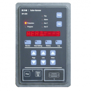
EATON MP-3000
RTD temperature with URTD module
Control features
Transition control for reduced voltage starters
Incomplete sequence (process feedback) detection and trip
Permits user-set number of cold starts
Limits number of starts per time
User sets minimum time between starts
Antibackspin (time from stop to next start) delay
Current-based process load shedding and restoration
Long acceleration timing feature
Motor stop input for synchronous motor and condenser
applications
Remote trip input
Differential trip input
Emergency override clears blocks to motor restarting (if
enabled)
Program settings while motor runs, with controlled change
over (if enabled)
Disarmed mode for commissioning and checking in a
running process
MP-3000 features and Enhancements
The MP-3000 Motor Protection Relay incorporates the field proven
motor thermal models and sequence component measurement
techniques that were pioneered in the IQ 1000 II relay thermal models.
The MP-3000 also adds several enhancements. Significant enhance
ments and features include:
1. Recognized to meet UL 1053 Standards for Ground Fault Protec
tion Devices.
2. Power supply operates continuously at 55% of nominal supply
voltage. It can ride through a voltage sag or loss for 30 cycles
without dropping out and taking the motor off line.
3. Optional Quick Release Drawout Case that makes removal and
replacement fast and easy.
4. New Armed/Disarmed feature for trip-free installation with Quick
Release Drawout Case.
5. User selectable trip or alarm only on relay internal failure detec
tion.
6. Real-time clock for date and time stamping of trips, alarms, and
events (Y2K compliant).
7. Expanded memory for extensive recording and logging of events,
trips, alarms, history, and motor starting current profiles.
8. Motor starting profile plot versus protection limits.
9. Easy-to-use faceplate and user interface. Settings and data are
organized into pages under six main modes. The modes are
Default (motor state), Monitor, View Setting, History, Logs, and
Program (change settings).
10. intel-i-trip Intelligent Overload Protection with adaptive trip char
acteristics based on RTD readings and motor operating history.
11. RTD diagnostics and communications error checking for addi
tional security against operation from RTD failures.
12. Mechanical Process Load Shedding feature provides overload
indication to control upstream processes, averting unnecessary
motor overload shutdown or jam trips, and maintaining process
continuity.
13. Download settings or retrieve metered and historical values via
the communications port.
14. Flexible user-configurable inputs and outputs for broader applica
tion.
15. Options for transition function control and monitoring on time
and/or current.
16. Emergency override function resets jogging limit functions and
clears thermal model bucket to permit restart with a time-tagged
event log. Unit uses a secured button; this function can be dis
abled.
17. Relay can be programmed while motor runs, and new settings
are all put into effect at once in a controlled fashion. Or, User can
set unit so programming is allowed only after motor stop.
1.3 Use of This Manual
This manual contains the following sections:
MP3010 Fixed Case, 5A CT 66D2205G01
MP3010INCOM Fixed Case, 5A CT, with INCOM Communications 66D2205G02
MP3010MODBUS Fixed Case, 5A CT, with Modbus Communications 66D2205G03
MP3010DEVICEN Fixed Case, 5A CT, with DeviceNet Communications 66D2205G04
MP3110 Fixed Case, 1A CT, Communications Capable with PONI 66D2205G05
MP3110INCOM Fixed Case, 1A CT, with INCOM Communications 66D2205G06
MP3110MODBUS Fixed Case, 1A CT, with Modbus Communications 66D2205G07
MP3110DEVICEN Fixed Case, 1A CT, with DeviceNet Communications 66D2205G08
MP3011 Drawout Case, 5A CT, No Communications 66D2207G01
MP3012 Drawout Case, 5A CT, with INCOM Communications 66D2207G02
MP3013 Drawout Case, 5A CT, with Modbus Communications 66D2207G03
MP3014 Drawout Case, 5A CT, with DeviceNet Communications 66D2207G04
MP3111 Drawout Case, 1A CT, No Communications 66D2207G05
MP3112 Drawout Case, 1A CT, with INCOM Communications 66D2207G06
MP3113 Drawout Case, 1A CT, with Modbus Communications 66D2207G07
MP3114 Drawout Case, 1A CT, with DeviceNet Communications 66D2207G08
MP3010VPI Fixed Case, 5A CT, with INCOM, URTD, and FOC 66D2036G51
MP3010VPM Fixed Case, 5A CT, with Modbus, URTD, and FOC 66D2036G52
MP3010VPD Fixed Case, 5A CT, with DeviceNet, URTD, and FOC 66D2036G53
MP3110VPI Fixed Case, 1A CT, with INCOM, URTD, and FOC 66D2036G54
MP3110VPM Fixed Case, 1A CT, with Modbus, URTD, and FOC 66D2036G55
MP3110VPD Fixed Case, 1A CT, with DeviceNet, URTD, and FOC 66D2036G56
Section 1 – Introduction – Describes the upgrade changes
from the existing IQ-1000II to the MP-3000. including retrofit
and new features list.
Section 2 – Product Overview – Benefits, feature list, use of
manual, and list of options.
Section 3 – Specifications – Provides hardware specifics
Section 4 – Operator Panel – Describes the pushbuttons,
LEDs, display window, and security door on the MP-3000’s
faceplate, plus the different modes of operation and detailed
mode description tables.
Section 5 – Programming the MP-3000 – Gives specific guid
ance for selecting setting values.
Section 6 – Installation and Wiring – Outlines procedures for
the plant electrician to follow when installing and wiring the
MP-3000.
Section 7 – Startup – Lists step-by-step procedures for ener
gizing the MP-3000 for the first time after installation.
Section 8 – Motor Thermal Protection Basics – Gives an
overview of how the hardware and software function to
gether to control, monitor, and protect the motor.
Section 9 – Application and Settings – Is intended as an aid
to the application engineer considering how and when to
apply the various features of the MP-3000.
Section 10 – Data Communications – Describes what is
needed for the MP-3000 to communicate with host com
puter systems.
Section 11 – Testing – Describes how to use the MP-3000
test functions and details recommended maintenance.
Section 12 – Troubleshooting – Provides information on how
to use the Operator Panel to recognize malfunctions. Also,
gives specific troubleshooting procedures.
Section 13 – Drawout Case Option – Describes installing and
using MP-3000 drawout case models.
When the User is familair with the basics of operating the MP-3000.
Tables 4.1 through 4.5 should be used as guides to program and
monitor the relay.
The following accessories and options are covered in other instruction
manuals