

Shinkawa Electric VM-3E2 Vibration Monitor Module
Shinkawa Electric VM-3E2 Vibration Monitor Module
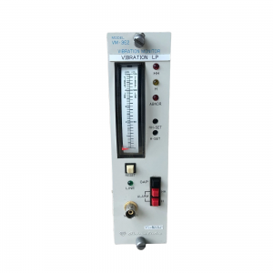
The Shinkawa Electric VM-3E2 Vibration Monitor Module is a high-reliability industrial monitoring device engineered to continuously measure and monitor shaft vibration, casing vibration, and mechanical dynamics of critical rotating machinery. Designed for seamless integration into plant safety and predictive maintenance architectures, the VM-3E2 safeguards high-value assets—such as steam turbines, gas turbines, large pumps, industrial compressors, and blowers—against catastrophic mechanical failure.
By converting raw transducer signals into precise real-time diagnostic data, the VM-3E2 enables plant operators to detect early mechanical unbalance, misalignment, and bearing wear before costly unplanned downtime occurs.
Technical Parameter List
| Parameter | Technical Specification |
| Manufacturer | Shinkawa Electric Co., Ltd. |
| Model | VM-3E2 Series |
| Input Signal Types | Eddy-current displacement probes, seismic accelerometers, velocity transducers |
| Measurement Channels | Dual-channel / Multi-channel configurable |
| Frequency Response | 10 Hz to 10 kHz (sensor dependent) |
| Analog Outputs | 4–20 mA DC proportional output |
| Relay Outputs | Configurable Alert (WARNING) & Danger (TRIP) contacts |
| Power Supply Requirements | 24 V DC (nominal) or 100–240 V AC (chassis dependent) |
| Accuracy Class | ±1.0% of full scale at reference temperature |
Product Features & Core Advantages
Real-Time Fault Detection: Continuous double-buffered signal processing guarantees instant relay triggering during abnormal vibration spikes.
Dual Alarm Thresholds: Features fully programmable Alert and Danger alarm setpoints with customizable trip-delay timing to prevent false trips caused by temporary process transients.
Immunity to Industrial Electrical Noise: High-grade optical and galvanic isolation protects signal paths from electromagnetic interference (EMI) commonly present near high-voltage motor drives.
VM-3E2
Flexible Transducer Pairing: Fully compatible with standard Shinkawa eddy-current sensors (such as the FK series) as well as third-party 3-wire vibration transmitters.
Diagnostic Signal Buffering: Includes front-panel raw buffered BNC outputs for direct connection to portable FFT analyzers during troubleshooting field runs.
Model Classification & Configuration Options
The VM-3E2 platform is available in several tailored hardware and firmware configurations to match specific monitoring needs:
VM-3E2-V (Vibration Amplitude): Configured specifically for overall shaft and housing peak-to-peak vibration displacement ($\mu\text{m}$ or mils).
VM-3E2-S (Speed / Phase): Dedicated module variant for keyphase signals, rotational speed (RPM), and phase-angle detection.
VM-3E2-A (Axial Position): Optimized for monitoring axial thrust position and rotor displacement relative to stationary casing.
Environmental Tolerance Conditions
Operating Temperature Range: -10°C to +65°C (+14°F to +149°F)
Storage Temperature Range: -30°C to +85°C (-22°F to +185°F)
Relative Humidity Limits: 5% to 95% RH (non-condensing)
Vibration Resistance: Designed to withstand continuous mounting-rack vibration up to $2\text{g}$ at 10–150 Hz.
Corrosion & Contamination Protection: Conformal coated printed circuit board (PCB) options available for harsh petrochemical environments.
Installation Method
Mounting: Insert the module into the dedicated slot of the Shinkawa 19-inch rack assembly or wall-mount chassis. Ensure the rear card connector aligns smoothly with the backplane before pressing firmly into place.
Fastening: Secure the top and bottom captive thumbscrews to ensure continuous chassis grounding and mechanical retention against operational vibration.
Wiring Connections: Wire input sensor leads using shielded twisted-pair (STP) cable. Connect the cable shield to the designated rack ground point at one end only to prevent ground loops.
Operating Instructions
Initial Calibration Check: Before commissioning, verify the sensor zero point and gain calibration using a simulated input signal or sensor zero reference gap voltage.
Alarm Resetting: In the event of an alarm latch, address the root-cause machine vibration before pressing the front-panel RESET button or asserting the remote digital reset pin.
Periodic Inspection: Every 12 months, inspect terminal block tightness, clean panel air intake filters, and check buffered BNC output health using an oscilloscope or analyzer.