

HIRSCHMANN RSB20-0800T1T1EAABHH Industrial Switch
HIRSCHMANN RSB20-0800T1T1EAABHH Industrial Switch
The Hirschmann RSB20-0800T1T1EAABHH is an unmanaged Basic Ethernet Rail Switch designed to provide high-reliability data communication for cost-sensitive, high-density industrial control environments.
As part of the streamlined RSB series, it features 8 standard RJ45 Fast Ethernet ports housed in a rugged, space-saving polymeric housing. Designed for immediate “plug-and-play” deployment, this unmanaged switch requires zero initial configuration, while maintaining Hirschmann’s rigorous standards for industrial durability, safety, and redundant power distribution.
Technical Parameter List
| Technical Parameter | Specification Value |
| Brand / Manufacturer | Hirschmann (A Belden Brand) |
| Model Code | RSB20-0800T1T1EAABHH |
| Total Port Count | 8 Ports |
| Port Interface Type | 8 x 10/100BASE-TX (RJ45 copper sockets) |
| Transmission Rate | 10/100 Mbit/s (Half-Duplex or Full-Duplex) |
| Transmission Distance | Up to 100 meters (using standard Cat5e/Cat6 copper cabling) |
| Operating Voltage | Redundant dual inputs: 9.6 VDC to 32 VDC |
| Current Consumption | Max. 190 mA at 24 VDC |
| Power Consumption | Max. 4.5 Watts |
| Signaling Contact | Integrated dry relay alarm contact (Max. 1 A at 24 VDC) |
| Protection Class | IP20 rating |
| Dimensions (W x H x D) | 47 mm x 135 mm x 111 mm |
| Weight | Approx. 180 g |
| Mounting Option | Standard 35 mm DIN Rail |
Product Features & Core Advantages
Optimized Cost-Efficiency: Provides full managed-equivalent hardware ruggedness in an unmanaged architecture, eliminating the software overhead cost for networks that do not require VLAN routing or SNMP control.
Dual Power Input Redundancy: Supports redundant 12/24 VDC connections. If primary terminal line power drops, the device immediately transitions to the secondary backup without dropping a packet.
Auto-Crossing & Auto-Negotiation: Each of the 8 RJ45 ports automatically identifies connected cabling types (straight-through vs. crossover) and operational transmission speeds (10 or 100 Mbps).
Vibration & Shock Proof: Designed without rotating cooling fans or internal moving components, making it highly immune to structural machinery vibrations.
Class 1 Div 2 Hazardous Safety: Fully certified for hazardous production areas containing explosive atmospheres.
Model Classification
The RSB20 family uses a specific product code matrix to define physical construction and port configurations:
All-Copper (Standard Density):
RSB20-0800T1T1…: 8 RJ45 copper ports (This Model).
Hybrid (Fiber Uplink Variants):
RSB20-0800M2M2…: 6 RJ45 copper ports + 2 Multi-Mode SC fiber ports.
RSB20-0800S2S2…: 6 RJ45 copper ports + 2 Single-Mode SC fiber ports for long-haul extensions.
Low-Density Units:
RSB20-0400…: Compact 4-port variations.
Environmental Tolerance Conditions
Operating Temperature: -40°C to +70°C (Hardened “E” operating range)
Storage & Transport Temp: -40°C to +85°C
Relative Humidity: 10% to 95% (Non-condensing)
Mechanical Vibrations: Meets IEC 60068-2-6 ($3.5\text{ mm}$ displacement at $2\text{ to }9\text{ Hz}$, $1\text{g}$ acceleration at $9\text{ to }150\text{ Hz}$).
Mechanical Shock: Meets IEC 60068-2-27 ($15\text{ g}$ peak force, $11\text{ ms}$ duration).
Industrial Certifications: cUL508. CE, FCC Class A, and ISA 12.12.01 Class 1 Division 2.
Installation Method
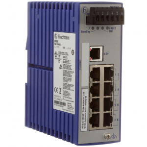
RSB20-0800T1T1EAABHH
1.Mount Device onto the DIN Rail:35 mm DIN Rail Installation。
Hook the upper slide of the RSB20 housing onto the top edge of your standard 35 mm DIN rail. Push down and press the bottom of the switch inward until the latch clicks securely onto the rail.
2.Connect the Chassis Earth Ground:ESD Protection。
Establish a connection between the ground terminal screw at the bottom of the front panel and your control panel’s master ground bar. Use a minimum of 14 AWG copper wire.
3.Wire the Power Terminal Connections:Redundant 12/24 VDC。
Insert stripped power wires into the positive (+) and negative (-) terminals of the removable 5-pin terminal block plug. If redundancy is desired, connect two independent power supply outputs to the primary (P1) and secondary (P2) terminals. Secure the terminal block screws.
4.Plug in Network Cables:RJ45 Copper Ports。
Plug your RJ45 Ethernet patch cables directly into the copper ports. The auto-crossing feature will resolve correct pin routing automatically.
Operating Instructions & Troubleshooting
Diagnostic LED Matrix
Power Indicator (P):
Green / Solid: Redundant power supplies are active and operating above minimum functioning voltage ($>9.6\text{ VDC}$).
Off: Loss of source power or terminal connection has come loose.
Fault Indicator (F):
Off: System operates without registering any active alarms.
Red / Solid: A configured alarm condition has triggered (e.g., loss of a monitored power line input or a specific port link drop).
Link/Activity (Ports 1 to 8):
Green / Solid: Device link established successfully.
Green / Flashing: Data packets actively transmitting on the physical port.
Off: No physical connection link is detected.
Dry Alarm Relay Operation
The integrated terminal block has a built-in alarm relay. In normal states, the relay contact remains closed.
If a tracked power failure occurs or the switch is completely powered down, the internal coil opens, signaling an immediate fault state directly to connected PLC monitor nodes.