OMRON FH-3050 FH Vision Controller
OMRON FH-3050 FH Vision Controller
When cancelling an operation or beginning operation, press the CLR Key sever
al times to return to the initial display.
After the SHIFT Key is pressed, changing the mode by means of the mode
change switch will cause the mode to change while retaining the current display.
When switching between RUN and PROGRAM, first go into MONITOR and
press the SHIFT Key again.
Programming Console Operations
3-3-1 Testing ID Communications
This operation can be used to show the status of errors generated by executing
either a read or a write communications operation repeatedly every second for a
specific Data Carrier address. In the read test, one byte is read from the Data
Carrier repeatedly, while in the write test one byte is written to the Data Carrier
repeatedly. This operation is possible in PROGRAM mode only.
Data contained in the Data Carrier will not be overwritten, so the test can be used
for checks and other operations at system startup. At the same time, this func
tion can also perform various adjustment tests, such as on-site adjustment of the
distance between the Data Carriers and the Read/Write Head.
1. Monitor the content of word SR 234 in the ID controller.
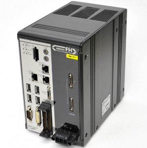
FH-3050
. Display bit SR 23209. and select the test mode (read or write) by turning
SR 23209 ON or OFF with the Set or Reset Key. (A read test is specified in
the following example.)
Read test: Turn OFF SR 23209.
Write test: Turn ON SR 23209
During the test, the T/R indicator for the ID function will flash, and the test
results will be placed in word SR 234. as shown below.
FFFF: ID communication in progress
0x00: Normal end
0xxx: Error end
4. Refer to ID Communications Errors on page 178 for the meaning of error
messages and error codes.
5. When the next communication is executed normally, the error display will
automatically leave the screen.
6. Turn off bit 23208 to cancel the test or before shifting to the another opera
tion. The following display shows a normal ending for the test
Reading the ID Error Log
When the ID Controller is running in the operating mode, information on various
types of errors is stored in the DM area in the ID Error Log and in the ID Error
Statistics Log. This information can be displayed on the Programming Console
as error messages.
ID Error Log
ID Error Statistics Log
The last 30 errors are displayed in order of the error log data number.
The numbers of ID communications errors generated are displayed by the type
of error.
Note The ID Error Log and ID Error Statistics Log may or may not be stored in memory
depending on ID Controller Setup. ID error log information is stored in one of two
ways, leaving either the newest error or the first 30 errors. Refer to 5-1 ID Con
troller Setup for details.
| RDIOR420 306713 Remote Digital Input/Output and relay KONGSBERG |
| 3500/93 Bently Nevada 3500/93 System Display |
| CI854AK01 3BSE030220R1 Communication interface module ABB |
| XVH-340-57MPI-1-13 EATON Control tableau |
| 8MSA4M.E3-86 B&R servo motor |
| 330104-01-08-10-01-05 Bently Nevada Proximity Probes |
| 330103-17-22-10-02-05 Bently Nevada 3300 XL 8 mm Probe |
| 330103-00-13-10-02-05 Bently Nevada 3300 XL 8 mm Probe |
| 330103-08-13-10-02-05 Bently Nevada 3300 XL 8 mm Probe |
| 330905-00-09-05-02-05 Bently Nevada 3300 XL 8mm Proximity Probe |
| 330130-045-01-05 Bently Nevada Extension Cable |
| 330102-20-55-10-02-RU 3300 XL 8 mm Proximity Probes Bently Nevada |
| 330103-00-17-10-02-05 Bently Nevada 3300 XL 8 mm Probe |
| 177230-01-01-RU Bently Nevada Seismic Transmitter |
| 330103-00-07-05-02-RU Bently Nevada Proximity Probes |
| 330103-00-07-10-02-05 Bently Nevada 3300 XL 8 mm Probe |
| 330750-60-RUBently Nevada High Temperature Velomitor System |
| 330130-080-12-RU Bently Nevada Extension Cable |