

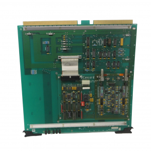
Honeywell TDC‑3000 BASIC,PLNM Plant Network Module,51401163‑100
TDC‑3000 BASIC,PLNM Plant Network Module,51401163‑100.
First, identify the electronics cabinets. These cabinets (towers) are shown in Figure
2-2 (and in Figure 2-1 with shaded lines). The towers look nearly identical, with a
translucent panel and a power switch near the middle-front of each cabinet. Tower #1
can be identified by two black cartridge drives installed near the top-front of its cabinet.
Tower #1 is also referred to as the “right 4-node” tower; tower #2 as the “left 4-node”
tower.
2. Do not place Color Monitors closer than 12” to each other.
3. Using Figures 2-1 and 2-2 as examples, place the towers in position, parallel to each
other. The printer must be positioned near tower #1 for connection to US #1. but
within the 6 foot length of the printer cable. Put the towers within 84 cm (33″) apart
(unless you have the optional 10 meter cable). Make sure both towers sit firmly on
level flooring
51401163‑100
Remove the rear center-section cover of both towers by removing four M5 flat-head
screws, exposing the I/O boards as shown in Figure 2-3. The cards seen in Figure 2-3
are a typical example for Tower #1. Note some connectors are not used and are only
outlined in Figure 2-3. The cables from these card connectors to the transition panels,
shown in Figure 2-5. will have been installed at the factory.
Note there are two TP485 cards, in slots 1 and 9. The TP485 in slot 9 of each tower
provides the TPLCN interface. The TP485 in slot 1 in each tower provides the
connection, at J3 (see Figure 2-4), and interface for thermocouples that sense the
module’s temperature (non-EC Compliant modules only)
The standard cabling connections you will make in the following steps are on the
transition panels in Figure 2-5. Note there are two exposed transition panels—one at
the top of the center section and another at the bottom (see Figure 2-5). The panel has
connectors and cable clamps on it that will be used to secure cables you will install.
Both towers have the same locations for specific connector/clamp brackets but the
bracket types in certain locations may differ depending on the options installed.
| GE | IS220YDOAS1A |
| GE | IS220YDOAS1A |
| GE | IS220PDOAH1B |
| GE | IS220YDIAS1A |
| GE | IS220PAOCH1B |
| SAMSON | TROVIS 6495-2 |
| BENDER | IRDH375-435 |
| BENDER | AGH150W-4 |
| ABB | 3BHE024855R0101 |
| ABB | 3BHB023302R0001 |
| ABB | 3BHE021951R0124 |
| EMERSON | CE3008 |
| EMERSON | CE4003S2B3 |
| EMERSON | CE3008 |
| EMERSON | CE4003S2B3 |
| EMERSON | CE5109 |
| KUKA | KSD1-16 |
| HONEYWELL | 05701-A-0301 |
| HONEYWELL | 05701-A-0302 |
| ABB | 3BHE021951R0124 |
| ABB | 3BHB023302R0001 |
| ABB | 3BHE024855R0101 |