

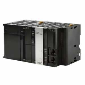
Omron NJ1019000 NJ1 programable logic controller
Omron NJ1019000
NJ1 programable logic controller built-in EtherNet/IP™ up to 32 connections, EtherCAT® up to 0 synchronous axes
Specifications
Controller functionality Sequence control
Max. number of synchronous axes 0
Max. number of axes (incl. virtual) 0
Primary task cycle time 1 ms
Program memory 3 MB
Variables memory 0.5 MB
Communication port(s) EtherCAT Master, EtherNet/IP, USB
Communication option(s) CAN, CompoNet Master, DeviceNet Master, DeviceNet Slave, EtherCAT Slave,
MODBUS Master, MODBUS Slave, PROFIBUS DP Master, PROFIBUS DP Slave, PROFINET Master, Serial RS-232C, Serial RS-422. Serial RS-485
Max. number of remote I/O nodes 64
I/O system CJ I/O Bus
Max. number of expansion units 40
Product Weight (unpacked) 627 g
Data Area Structure
When designating a data area, the acronym for the area is always required for
any but the IR and SR areas. Although the acronyms for the IR and SR areas are
often given for clarity in text explanations, they are not required, and not entered,
when programming. Any data area designation without an acronym is assumed
to be in either the IR or SR area. Because IR and SR addresses run consecu
tively, the word or bit addresses are sufficient to differentiate these two areas.
An actual data location within any data area but the TC area is designated by its
address. The address designates the bit or word within the area where the de
sired data is located. The TC area consists of TC numbers, each of which is used
for a specific timer or counter defined in the program. Refer to 3-8 TC Area for
more details on TC numbers and to 5-13 Timer and Counter Instructions for in
formation on their application.
The rest of the data areas (i.e., the IR, SR, HR, DM, AR, and LR areas) consist of
words, each of which consists of 16 bits numbered 00 through 15 from right to
left. IR words 000 and 001 are shown below with bit numbers. Here, the content
of each word is shown as all zeros. Bit 00 is called the rightmost bit; bit 15. the
leftmost bit.
NJ1019000
The term least significant bit is often used for rightmost bit; the term most signifi
cant bit, for leftmost bit. These terms are not used in this manual because a
single data word is often split into two or more parts, with each part used for dif
ferent parameters or operands. When this is done, the rightmost bits of a word
may actually become the most significant bits, i.e., the leftmost bits in another
word,when combined with other bits to form a new word.
he DM area is accessible by word only; you cannot designate an individual bit
within a DM word. Data in the IR, SR, HR, AR, and LR areas is accessible either
by word or by bit, depending on the instruction in which the data is being used.
To designate one of these areas by word, all that is necessary is the acronym (if
required) and the two-, three-, or four-digit word address. To designate an area
by bit, the word address is combined with the bit number as a single four- or five
digit address. The following table show examples of this. The two rightmost dig
its of a bit designation must indicate a bit between 00 and 15. i.e., the rightmost
digit must be 5 or less the next digit to the left, either 0 or 1.
The same TC number can be used to designate either the present value (PV) of
the timer or counter, or a bit that functions as the Completion Flag for the timer or
counter. This is explained in more detail in 3-8 TC Area.
Area Word designation
Bit designation
000 00015 (leftmost bit in word 000)
Not possible
TC 215 (designates PV) TC 215 (designates completion flag)
LR LR 12 LR 1200
Word data input as decimal values is stored in binary-coded decimal (BCD);
word data entered as hexadecimal is stored in binary form. Each four bits of a
word represents one digit, either a hexadecimal or decimal digit, numerically
equivalent to the value of the binary bits. One word of data thus contains four
digits, which are numbered from right to left. These digit numbers and the corre
sponding bit numbers for one word are shown below.
3 2 1 0
15 14 13 12 11 10 09 08 07 06 05 04 03 02 01 00
0 0 0 0 0 0 0 0 0 0 0 0 0 0 0 0
When referring to the entire word, the digit numbered 0 is called the rightmost
digit; the one numbered 3. the leftmost digit.
When inputting data into data areas, it must be input in the proper form for the
intended purpose. This is no problem when designating individual bits, which