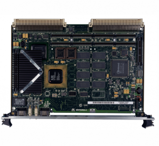
MOTOROLA MVME2400 Series VME Processor Module
PowerPC 750™ 32-bit microprocessor
32KB/32KB L1 cache
1MB backside L2 cache
32MB to 512MB of on-board ECC SDRAM
Up to 1MB capacity for on-board firmware
or user-specified requirements
8MB on-board Flash memory for user
specified requirements
On-board debug monitor with self-test
diagnostics
Two 32/64-bit PMC expansion slots with
front panel and P2 I/O
64-bit PCI expansion mezzanine
connector
8K x 8 NVRAM and time-of-day clock with
replaceable battery backup
One asynchronous serial debug port
Four 32-bit timers, one 16-bit timer, one
watchdog timer
10/100Mb/s Ethernet interface
4-level requester, 7-level interrupter, and
7-level interrupt handler for VMEbus
Low-power, high-performance microprocessor suitable for a variety of
applications
The MVME2400 series of VME boards provides the performance of Motor
ola’s PowerPlus II Architecture and the ability to be fully customized to satisfy
your application needs with two PCI Mezzanine Cards (PMCs). The flexibility
of the MVME2400 provides an excellent base platform that can be quickly
and easily customized for a variety of industry-specific applications.
Utilizing Motorola’s low-power, high-performance PowerPC 750 microproces
sors, the Peripheral Component Interconnect (PCI) bus for the on-board
peripherals, processor/memory bus to PCI bus bridge, and a VME interface,
the MVME2400 processor modules pack optimum levels of flexibility and per
formance into a single VME slot.
IEEE P1386.1 Compliant PMC Slots
The MVME2400 features dual PMC ports with support for
both front-panel and P2 I/O. P2 I/O-based PMCs which follow
the PMC committee recommendation for PCI I/O when using
the VME64 extension connector will be pin-out compatible
with the MVME2400.
In addition to providing high-performance expansion I/O, the
IEEE P1386.1 compliant PMC ports form a common architec
ture for future generations of products. Changing I/O require
ments can be satisfied by simply replacing PMCs while
reusing the same base platform, reducing the long-term cost
Motorola MVME2400 Series VME Processor Module
of ownership.
VME64 Extension Connector
To maximize the capabilities of the MVME2400. 5-row 160
pin DIN connectors replace the 3-row 96-pin connectors his
torically used on VME for P1 and P2. Two rows, Z and D,
have been added to the VME P1/J1 and P2/J2 connectors
providing a user with additional I/O. The VME64 extension
connector is 100% backward compatible with existing VME
card systems.
PowerPlus Architecture
A second-generation architecture, PowerPlus II Architecture
is a processor and bus architecture fully optimized to get the
maximum performance from the PowerPC microprocessor
family, the PCI bus, and the VMEbus. Features added to the
original PowerPlus Architecture include support for 100 MHz
local bus operation, and utilization of synchronous DRAM
(SDRAM) technology. The outstanding performance of VME
processor boards based on the PowerPlus II Architecture is
not due to a single factor. A number of elements in the design
of the PowerPlus II Architecture contribute to its outstanding
performance including the Processor/Memory subsystem,
high-speed local bus, optimally decoupled architecture,
decoupling the processor from PCI, and the advanced VME
interface which reduces PCI delays.
MVME2400
Part Number
Description
All modules include 1MB backside L2 cache, 9MB Flash, and the
option of either the original VME Scanbe front panel and handles or
the IEEE 1101 compatible front panel with injector/ejector handles.
MVME2401-1 233 MHz MPC750. 32MB ECC SDRAM, Scanbe
handle
MVME2401-3 233 MHz MPC750. 64MB ECC SDRAM, IEEE
handle
MVME2403-1 233 MHz MPC750. 32MB ECC SDRAM Scanbe
handle
MVME2403-3 233 MHz MPC750. 32MB ECC SDRAM, IEEE
handle
MVME2431-1 350 MHz MPC750. 32MB ECC SDRAM, Scanbe
handle
MVME2431-3 350 MHz MPC750. 32MB ECC SDRAM, IEEE
handle
MVME2432-1 350 MHz MPC750. 64MB ECC SDRAM, Scanbe
handle
MVME2432-3 350 MHz MPC750. 64MB ECC SDRAM, IEEE
handle
MVME2433-1 350 MHz MPC750. 128MB ECC SDRAM,
Scanbe handle
MVME2433-3 350 MHz MPC750. 128MB ECC SDRAM, IEEE
handle
MVME2434-1 350 MHz MPC750. 256MB ECC SDRAM,
Scanbe handle
MVME2434-3 350 MHz MPC750. 256MB ECC SDRAM, IEEE
handle
MVME2400-0321 450 MHz MPC750. 32MB ECC SDRAM, Scanbe
MVME2400-0323 450 MHz MPC750. 32MB ECC SDRAM, 1101
MVME2400-0331 450 MHz MPC750. 64MB ECC SDRAM, Scanbe
MVME2400-0333 450 MHz MPC750. 64MB ECC SDRAM, 1101
MVME2400-0341 450 MHz MPC750. 128MB ECC SDRAM,
Scanbe
MVME2400-0343 450 MHz MPC750. 128MB ECC SDRAM, 1101
MVME2400-0351 450 MHz MPC750. 256MB ECC SDRAM,
Scanbe
MVME2400-0353 450 MHz MPC750. 256MB ECC SDRAM, 1101
MVME2400-0361 450 MHz MPC750. 512MB ECC SDRAM,
Scanbe
MVME2400-0363 450 MHz MPC750. 512MB ECC SDRAM, 1101
Related Products
PMCSPAN-002 Primary PCI expansion, mates directly to the
MVME2400 providing slots for either two single
wide or one double-wide IEEE P1386.1 compli
ant PMC cards; optional PMCSPAN-010
PMCSPAN(1)-002 PMCSPAN-002 with original VMEbus Scanbe
handles
PMCSPAN-010 Secondary PCI expansion, plugs directly into
PMCSPAN-002 providing two additional PMC
slots
PMCSPAN(1)-010 PMCSAN-010 with original VMEbus Scanbe
handles
MPMCxxx Motorola’s family of PMC modules; ask your
sales representative for details
Documentation
V2400A/IH MVME2400 Installation and Use
V2400A/PG MVME2400 Programmer’s Reference Guide
PMCSPANA/IH PMCspan Installation and Use
PPCBUGA1/UM PPCBug User’s Manual, Part 1 of 2
PPCBUGA2/UM PPCBug User’s Manual, Part 2 of 2
PPCDIAA/UM Firmware Diagnostics Manual