Woodward: CONTROL-LS-521-5/P1 8440-2150
Product number: 8440-2150
Manufacturer product number: 8440-2150
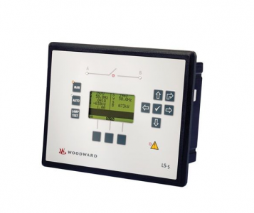
Description: Woodward: CONTROL-LS-521-5/P1. 5A, Version 2
Predecessor: 8440-1947
Application
The LS-5 Series has no internally isolated power supply.
For marine applications an EMI filter (i.e. SCHAFFNER – FN 2070-3-06) must be connected ahead of the power
supply input.
To meet the functional safety requirements of the application, the rules of marine classification independent protec
tive devices must be applied.
Clamp Fastener Installation
For installation into a panel door with the fastening clamps, please proceed as follows:
1. Panel cutout
Cut out the panel according to the dimensions in Figure 2-1.
Note: It is not necessary to drill the holes if the fastening clamps are used.
2. Remove terminals
Loosen the wire connection terminal screws on the back of the unit and
remove the wire connection terminal strip if required.
3. Insert screws in clamps
Insert the four clamping screws into the clamp inserts from the shown
side (opposite of the nut insert) until they are almost flush. Do not com
pletely insert the screws into the clamp inserts.
4. Insert unit into cutout
Insert the unit into the panel cutout. Verify that the unit fits correctly in
the cutout. If the panel cutout is not big enough, enlarge it accordingly.
5. Attach clamp inserts
Re-install the clamp inserts by tilting the insert to a 45° angle. (1) Insert
the nose of the insert into the slot on the side of the housing. (2) Raise the
clamp insert so that it is parallel to the control panel.
6. Tighten clamping screws
Tighten the clamping screws (1) until the control unit is secured to the
control panel (2). Over tightening of these screws may result in the clamp
inserts or the housing breaking. Do not exceed the recommended tighten
ing torque of 0.1 Nm (0.9 pound-force inches).
8440-2150
7. Reattach terminals
Reattach the wire connection terminal strip (1) and secure them with the
side screws.
Screw Kit Installation
In order to enhance the protection of the front to IP 65. it is possible to fasten the unit with a screw kit instead of
the clamp fastener hardware.
Proceed as follows to install the unit using the screw kit:
1. Cut out the panel and drill the holes according to the dimensions in Figure 2-3.
2. Insert the unit into the panel cutout. Verify that the unit fits correctly in the cutout. If the panel cutout is
not big enough, enlarge it accordingly.
3. Insert the screws and tighten to 0.6 Nm (5.3 pound inches) of torque. Tighten the screws with a cross
wise pattern to ensure even pressure distribution.
The phasor diagram is used from the System B view. Power factor is defined as follows.
+ Positive
Power Factor is defined as a ratio of the real power to apparent power. In a purely resistive circuit, the voltage
and current waveforms are instep resulting in a ratio or power factor of 1.00 (often referred to as unity). In an in
ductive circuit, the current lags behind the voltage waveform resulting in usable power (real power) and unusable
power (reactive power). This results in a positive ratio or lagging power factor (i.e. 0.85lagging). In a capacitive
circuit, the current waveform leads the voltage waveform resulting in usable power (real power) and unusable
power (reactive power). This results in a negative ratio or a leading power factor (i.e. 0.85leading).
Inductive: Electrical load whose current waveform
lags the voltage waveform thus having a lagging
power factor. Some inductive loads such as electric
motors have a large startup current requirement result
ing in lagging power factors.
Capacitive: Electrical load whose current waveform
leads the voltage waveform thus having a leading
power factor. Some capacitive loads such as capacitor
banks or buried cable result in leading power factors.
Different power factor displays at the unit:
i0.91 (inductive)
lg.91 (lagging)
c0.93 (capacitive)
ld.93 (leading)
Reactive power display at the unit:
70 kvar (positive)
Output at the interface:
+ (positive) -60 kvar (negative) – (negative
| GE | IC698CRE030 |
| GE | 8106-TI-RT |
| GE | 8810-HI-TX-01 |
| GE | 8101-HI-TX-02 |
| GE | IS200VCRCH1B |
| GE | IS200VTURH2BAC |
| GE | IS200VRTDH1D |
| GE | IS215UCVEH2AE |
| GE | IS215VPROH1BD |
| GE | IS200VTCCH1CBB |
| GE | IC695CPU315-CD |
| GE | IS220PAICH2A |
| GE | DS200KLDBG1ABC |
| GE | DS200SDCCG1AEC |
| GE | DS200SLCCG1ACC |
| GE | DS200SLCCG1AEE |
| GE | IC660ELB912 |
| GE | DS200ADPBG1ABB |