Woodward 8440-2082 EasyGen 3200XT Genset Controller
Woodward 8440-2082 EasyGen 3200XT Genset Controller
The easYgen-3000XT offers four operation modes:
n AUTO
n MANUAL (MAN)
n TEST
n STOP
n … and an internal (non) operating phase during starting the
device itself
The plastic housing (HMI) version of the easYgen-3000XT enables
to select an operation mode by pressing the according button at
the front panel – if current settings allow this function.
For more information about the operation modes please see
Ä Chapter 5.2 “Change Operating Modes” on page 460.
Mount Unit (Plastic Housing)
Mount the unit either using the clamp fasteners (Ä Chapter 3.2.1
“Clamp Fastener Installation” on page 42) or the screw kit
(Ä Chapter 3.2.2 “Screw Kit Installation” on page 43).
Clamp Fastener Installation
For installation into a door panel with the fastening clamps, pro
ceed as follows:
Fig. 13: Remove terminals
Fig. 14: Insert screws in clamps
Cut out the panel according to the dimensions in Fig. 12、
Loosen the wire connection terminal screws on the back of
the unit and remove the wire connection terminal strip if
required.
Insert the four clamping screws into the clamp inserts from
the shown side (Fig. 14; opposite the nut insert) until they are
almost flush. Do not completely insert the screws into the
clamp inserts.
Insert the unit into the panel cutout. Verify that the unit fits
correctly in the cutout. If the panel cutout is not big enough,
enlarge it accordingly
Re-install the clamp inserts by tilting the insert to a 45° angle.
(Fig. 15/1) Insert the nose of the insert into the slot on the
side of the housing. (Fig. 15/2) Raise the clamp insert so that
it is parallel to the control panel.
Tighten the clamping screws (Fig. 16/1) until the control unit
is secured to the control panel (Fig. 16/2). Over tightening of
these screws may result in the clamp inserts or the housing
breaking. Do not exceed the recommended tightening torque
of 0.1 Nm.
Reattach the wire connection terminal strip (Fig. 17) and
secure them with the side screws.
Proceed as follows to install the unit using the screw kit:
Cut out the panel and drill the holes according to the dimen
sions in Fig. 18 (dimensions shown in mm).
Insert the unit into the panel cutout. Verify that the unit fits
correctly in the cutout. If the panel cutout is not big enough,
enlarge it accordingly.
Insert the screws and tighten to 0.6 Nm (5.3 pound inches) of
torque
The device terminals are allocated (similarly for all housing var
iants) as follows:
n Plastic housing – for easYgen-3200XT-P1 and
easYgen-3200XT-P1-LT
n Sheet metal housing – for easYgen-3100XT-P1
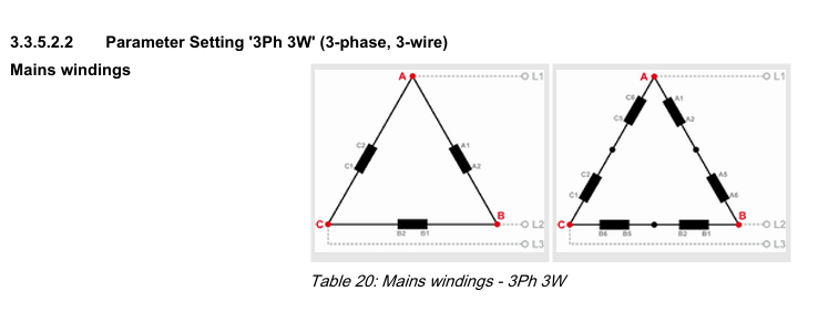
Parameter Setting ‘3Ph 4W OD’ (3-phase, 4-wire, Open delta)
Generator windings
A generator system that is connected to the load through a 3
phase, 4-wire connection but have the device wired for a 3-phase,
3-wire installation may have the L2 phase grounded on the secon
dary side. In this application the device will be configured for 3
phase, 4-wire OD for correct power measurement.