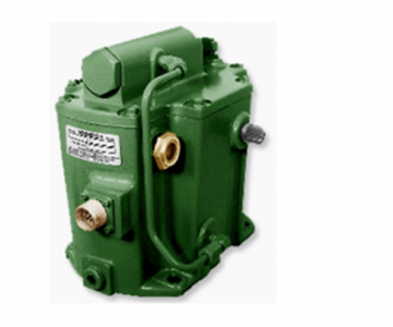
Woodward TG-10E, -13E, and –17E Actuator 9904-110
This manual 04045 provides general information, installation, operation,
principles of operation, and troubleshooting for the Woodward TG-10E,
TG-13E, and TG-17E Actuators.
All actuators have the same mounting pad, drive shaft configuration, and terminal
shafts.
Rated work capacity is 10 lb-ft (14 Nm) for the TG-10E and 13 lb-ft (18 Nm) for
the TG-13E, both with 150 psi (1034 kPa) internal operating oil pressure. The
TG-17E offers 18 lb-ft (24 Nm) rated work capacity with higher 200 psi (1379
kPa) oil operating pressure.
Maximum terminal shaft travel for the TG-10E is 30 degrees, and 40 degrees for
the TG-13E/-17E. Recommended travel from “NO LOAD” to “FULL LOAD” is 2/3
of maximum terminal shaft travel, or 20 degrees for the TG-10E, and 30 degrees
for the TG-13E/-17E. (See Figure 2-1. Recommended Terminal Shaft Travel.)
The internal pump is sized to operate over standard speed ranges: 1100 to 2400
rpm; 2400 to 4000 rpm; 4000 to 6000 rpm. The actuator is built for the speed
range specified by the customer. The high-speed actuator (4000 to 6000 rpm)
may require a heat exchanger in some applications. (See Chapter 2. When is a
Heat Exchanger Necessary?)
All other operating features and specifications of the TG actuators are the same
for each model.
Description
The TG actuator is a self-contained, proportional, electrohydraulic actuator used
for the positioning of valves. It can be used with all available Woodward
integrating electronic controls and accessories.
The TG proportional electrohydraulic actuator is a transducer which converts a
given electrical signal to a corresponding proportional angular output shaft
position to control the flow of steam or energy medium to the turbine. The
actuator is controlled by an external signal from an integrating amplifier. The
control signal must be unidirectional dc, thereby proportionally increasing the
mechanical output position. The exact control used depends upon the operating
scheme of the installation. Control assemblies are available to control speed,
frequency, load, pressure, and other variables.
Optional Actuators
A TG actuator is available which does not require a drive from the turbine (Figure
2-4). It uses an external, customer-supplied, hydraulic source and can be located
in a convenient location to operate the steam valve linkage.
Also available is an electric motor-driven TG actuator (Figure 2-5) which can be
mounted in a convenient location and does not require a mechanical drive from
the turbine or an external oil supply.
A UL Listed TG (Class I, Division 2. Groups B, C, and D), is also available for use
in hazardous areas
TGE
Introduction
This chapter describes receiving, storage, and installation requirements for the
TG actuator.
Use care while handling and installing the TG actuator. Be particularly careful to
avoid striking the drive shaft, terminal shafts, or the electrical connector. Abuse
can damage seals, internal parts, and factory adjustments. Do not rest the
actuator on its drive shaft.
Receiving
The TG actuator is shipped from the factory boxed and bolted to a wooden
platform in the vertical position. The oil sight gauges are factory installed on the
sides of the case, and a breather/filler cap is positioned on the cover for vertical
or horizontal actuator mounting and operation.
After factory testing and adjusting, the TG actuator is drained of oil, sealed, and
painted. This leaves a light film of oil covering internal parts to prevent rust.
External shafts are coated with a spray lubricant. No internal cleaning or flushing
is necessary before installation and operation.
Storage
The TG actuator may be stored for short periods of time as received from the
factory. For long-term storage, storage in an environment with large temperature
changes , humid or corrosive atmosphere, etc., or if the actuator is installed on
the turbine for storage, fill the actuator with oil and follow preservation packaging
instructions in Woodward manual 25075. Commercial Preservation Packaging for
Storage of Mechanical-Hydraulic Controls.
If the breather/filler cap has been set for horizontal governor operation and the
actuator is to be stored vertically, replace the cap with a plug before filling it with
oil to prevent oil from draining through the vent hole.
Drive Shaft Rotation
The actuator rotation is single rotation only. When looking at the actuator from
the top, the direction of rotation must be the same as the turbine shaft or the
electric motor driving the oil pump. The arrows on the actuator base indicate the
actual direction of rotation, when viewing in that plane. Use the following
procedure to change the direction of rotation of the oil pump:
1. Remove the four pump housing screws.
2. Rotate the pump housing assembly 180 degrees.
3. Align the arrows on the pump housing with the pointer on the actuator case.
The arrows indicate the actual pump drive shaft rotationTGE13. 2400 rpm
9904-110
TGE13. 4000 rpm
9904-111
TGE13. 6000 rpm
9904-112
TGE17. 2400 rpm
9904-113
TGE17. 4000 rpm
9904-114
TGE17. 6000 rpm
*Documentation: Product Spec: 04044. Manual: 04045
9904-115