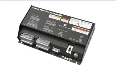
Woodward SPC Servo Position Controller 8200-226 8200-227
SPC – Configurable Servo/Actuator Driver, Marine Certified
8200-226
SPC – Configurable Servo/Actuator Driver, CANOpen Comm
8200-227
Optional Mounting Bracket – Vertical
*Documentation: Product Spec: 03254. Manual: 26236
8928-7334
The SPC (Servo Position Controller) is available in two model configurations:
8200-226: DeviceNet Control with Analog Backup (or Analog primary demand)
8200-227: CANopen Control with Analog Backup (or Analog primary demand)
Models 8200-224 & 8200-225 are inactive and replaced by above item numbers.
The SPC positions a hydraulic or pneumatic actuator based on a position demand signal received from a
control. The SPC positions a single-coil actuator using single or dual position feedback devices. The
position demand signal can be sent to the SPC via DiviceNet or CANopen, (4 to 20) mA, or both. A
software program running on a Personal Computer (PC) allows the user to easily configure and calibrate
the SPC.
The SPC Service Tool is used to configure, calibrate, adjust, monitor, and troubleshoot an SPC. The
service tool runs on a PC and communicates with the SPC through a serial connection. The serial port
connector is a 9-pin sub-D socket and uses a straight-through cable to connect to the PC. Woodward
offers a USB to 9-pin Serial Adapter kit if needed for new computers that do not have a 9-pin serial
connector (P/N 8928-463). This kit contains a USB adapter, software, and a 1.8 m (6 feet) serial cable.
(See Chapter 4 for SPC Service Tool installation instructions.)
The SPC is configured by using the SPC Service Tool’s configuration file editor to create a file that is then
loaded into the SPC. The SPC Service Tool can also read an existing configuration from an SPC into the
configuration file editor.
See Chapter 4. SPC User’s Guide, for detailed instructions on using the SPC Service Tool.
The first time an SPC is connected to an actuator, it must be calibrated to the actuator’s position feedback
transducer. The user is guided through the calibration process by the service tool. Calibration can also be
performed by the control via the Digital Control link (DiviceNet or CANopen). The calibration procedure
can be found in the GAP help file.
SPC
Power Requirements
The SPC requires a voltage source of (18 to 32) V (dc), with a current capacity of 1.1 A max. If a battery
is used for operating power, a battery charger is necessary to maintain a stable supply voltage. The
power line should be protected with a 5 A, 125 V fuse capable of withstanding a 20 A, 100 ms in-rush
when power is applied.
Location Considerations
Consider these requirements when selecting a mounting location for the SPC:
• Adequate ventilation for cooling
• Space for servicing and repair
• Protection from direct exposure to water
• Protection from high-voltage or high-current devices, or devices which produce electromagnetic
interference
• Avoidance of vibration
• Selection of a location that will provide an operating temperature range of
(–40 to +70) °C / (–40 to +158) °F
Optional SPC Mounting Kit
Optionally, SPC mounting bracket kit #8928-7334 is available for use in reducing required panel mounting
space within a cabinet. Ideal for applications where multiple SPCs are utilized, this bracket allows SPCs
to be mounted such that they protrude vertically into the cabinet, reducing the required panel mounting
area. This bracket’s design allows users to first attach the SPC to the bracket, then install the entire
assembly onto a cabinet side panel. Please refer to
Shields and Grounding
A shield termination is provided at the terminal block for each of the signals. All of these inputs should be
wired using shielded, twisted-pair wiring. The exposed wire length beyond the shield should be limited to
one 25 mm (1 inch). The shield should be terminated at only one end in order to avoid creating a ground
loop