

SAUTER AVM115F120 Linear Valve Actuator
necting the voltage to terminals MM/N and 01. When dismantling, first the actuator and valve spindles
are released, then the cap nut. The device is delivered ex works in the middle position.
The concept of synchronous motor and magnetic coupling enables parallel operation of multiple valve
actuators of the same type.
The maximum accessory equipment for an actuator is 1 auxiliary change-over contact or 1 potentiom
eter.
The auxiliary contact accessory is screwed onto the top cover of the actuator. To be able to make the
mechanical connection, you first have to remove the indicator knob. A new indicator can be seen on
the cover of the accessory.
AVM 105. 115: Valve actuator
How energy efficiency is improved
Torque-dependent cut-off facility for efficient usage of energy
Features
• Activation of 2-way and 3-way valves of the VUN/BUN, VUD/BUD and VUE/BUE series
• For controllers with a switching (2-/3-point) output
• Synchronous motor with electronic control unit and time-dependent cut-off
• Direction of operation can be selected directly on the cable
•Maintenance-free gearbox with magnetic coupling
• Gear unit can be disengaged in order to position the valve by hand (hexagon key provided)
• Connection with valve spindle performed automatically
• Cap nut for valve fitting made of brass
• Fitting vertically upright to horizontal, not suspended
Type
AVM115F122
AVM115F901
Actuating power (N)
500
500
51.361
Voltage
24 V~
230 V~
Running time (s)
120
160
Power consumption
1.6 W, 1.7 VA
2.0 W, 4.0 VA
A AVM115F901: For SAUTER Valveco VCL040 and VCL050. inverse scale, inverse connection
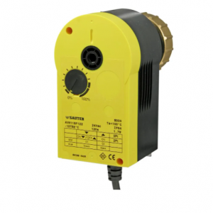
AVM115F120
| GE | MULTILIN SR-489-P5-HI-A20-T |
| KUKA | KSD1-16 00-122-284 |
| SAACKE | SAACKE F-GDSA |
| BENTLY NEVADA | 3500/22 288055-01 |
| Beckhoff | C6920-0050 |
| PEOSOFT | PTQ-PDPMV1 |
| GE | HYDRAN_M2-H2 |
| GE | H201TI_CE-H2 |
| GE | MMLG01 |
| GE | MMLG02 |
| GE | MMLB01 |
| GE | MVAJ105RA0802A |
| GE | IS200TRPGH1B |
| ABB | PCD231 3BHE025541R0101 |
| ABB | PCD235 3BHE032025R0101 |
| AMC | P111-6052 |
| MOOG | D635-706 |
| ABB | SCA022657R8790 CU2A01V2 |
| CTI | 2500-C200 |
| GE | IS200ESYSH1AAA |
| GE | IS200EDISG1AAA |
| SAUTER | AVM234SF132-5 |
Accessories
Type
0372145001
0372145002
0372249001
0372273001
0372286001
0372286002
0372286003
0372320001
0372459100
0372459102
Description
Auxiliary change-over contacts, single
Auxiliary change-over contacts, double
Temperature adapter for AVM 321(S), media temperature > 100…130 °C
Adapter for Siemens valve VVG/VXG 44. 48
Potentiometer, 130 Ω
Potentiometer, 1000 Ω
Potentiometer, 5000 Ω
Hexagon key as visualisation for position indicator
External switching, 230 V version for parallel operation with A*M 1*4 or actuators with end
switch, incl. junction box
External switching, 24 V version for parallel operation with A*M 1*4 or actuators with end
switch, incl. junction box
A Auxiliary change-over contacts: Infinitely variable 0…100%, admissible load 5(2) A, 24…230 V
A Potentiometers: Only one potentiometer or one set of auxiliary contacts can be fitted for each actuator
Description of operation
When voltage is applied to the cable, the control unit to be activated is moved to any desired position
by means of the coupling rod.
Direction of the stroke for 3-point control:
• The coupling rod moves out and the valve opens when the actuator is connected to the voltage via
the blue (MM/N) and brown (01) cables.
• The coupling rod moves in and the valve closes when the actuator is connected to the voltage via
the blue (MM/N) and black (02) cables.
With 3-point control, the direction of the stroke is changed by swapping the connections.
Direction of the stroke for 2-point control (there is always voltage on the black cable 02):
• The coupling rod moves out and the valve opens when the actuator is connected to the voltage via
the blue (MM/N) and brown (01) cables.
• The coupling rod moves in and the valve closes when the actuator is connected to the voltage via
the blue (MM/N) cable, and the brown (01) cable is not connected to the voltage.
In the end positions (limit stop in valve or maximum stroke reached) or in the case of an overload, the
magnetic coupling is activated. The positioning signal is switched off by the electronic cut-out after 3
minutes or 60 seconds (F100).
The manual adjustment is performed by releasing the gear unit (slide switch beside the connection
cable) and simultaneously turning it with the hex spanner on the top part of the actuator. 8 mm stroke
achieved with 1½ turns. The actuator position can be determined by looking at the actuator bracket or
the indicator knob on the top part of the actuator