

SAUTER AVF234SF132 Linear valve actuator AVM 234S series
Description of operation
After a restart or a start after triggering the reset (terminal 21), a waiting time of up to 45 s elapses
until the actuator is available again. Depending on the type of connection (see connection diagram),
the actuator can be used as a continuous (0…10 V or 4…20 mA), 2-point (OPEN/CLOSE) or 3-point
actuator (OPEN/STOP/CLOSE).
The running time of the actuator can be set with switches S1 and S2 according to the relevant re
quirements. Switches S3 and S4 are used to configure the characteristic (equal-percentage, linear or
quadratic).
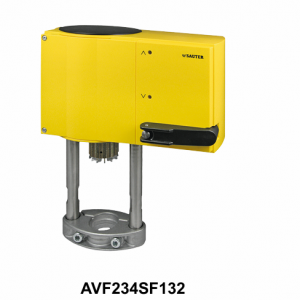
AVF234SF132
The external crank handle enables manual positional setting. When the crank handle is folded out,
the motor is switched off. After the crank handle is folded back, the spring function is active again and
the actuator moves to the target position (without initialisation). When the crank handle is folded out,
the actuator remains in this position.
Intended use
This product is only suitable for the purpose intended by the manufacturer, as described in the “De
scription of operation” section.
All related product regulations must also be adhered to. Changing or converting the product is not ad
missible.
Engineering and fitting notes
Condensate, dripping water, etc. must be prevented from entering the actuator along the valve spin
dle.
The actuator is mounted directly on the valve and fixed with screws (no further adjustments are re
quired). The actuator is connected with the valve spindle automatically. Depending on the type and
how it is delivered ex works, the stroke of the actuator spindle is 0% or 100%.
The housing contains three break-out cable inlets which are broken out automatically when the cable
inlet is screwed in.
The concept of DC motor/electronics enables parallel operation of multiple valve actuators of the
same type. The cross-section of the power cable must be selected based on the cable length and the
number of actuators. With five actuators wired in parallel and a cable length of 50 m, we recommend
a cable cross-section of 1.5 mm2 (power consumption of the actuator × 5).
The maximum equipment for the actuator is one 230 V module, one additional accessory component
(auxiliary contact or potentiometer) and the split-range unit.
Outdoor installation
We recommend protecting the devices from the weather if they are installed outside buildings.
Initialisation and feedback signal
The actuator initialises itself autonomously, whether continuous, 2-point or 3-point. Once a voltage is
applied to the actuator for the first time and the waiting time has elapsed, the actuator moves to the
lower limit stop of the valve and thus enables automatic connection with the valve spindle. Then it
moves to the upper stop and the value is detected and saved via a travel measurement system. The
control signal and the feedback are adjusted to this effective stroke. After a power failure or a spring
return, no re-initialisation is carried out. The values remain saved
For a re-initialisation, the actuator must be connected to the power supply and there must be a con
stant input signal at 3u or 3i. An initialisation is triggered by folding the crank handle out and back
twice within 4 s. Then the two LEDs flash red.
During initialisation, the feedback signal is inactive or equal to the value “0”. Initialisation is carried out
with the shortest running time. The re-initialisation is only valid when the whole process is complete.
Folding the crank handle out again interrupts this process.
If the valve actuator detects jamming, it reports this by setting the feedback signal to 0 V after approx.
90 s. During this time, the actuator tries to overcome the jamming. If the jamming can be overcome,
the normal control function is activated again, and the feedback signal is restored.
Spring return
If the supply voltage fails or is switched off, or if a monitoring contact at terminal 21 is activated, the
brushless DC motor releases the gear unit and the preloaded spring moves the actuator to the rele
vant end position (depending on the model). In the process, the control function of the actuator is
locked for 45 s (both LEDs light up green) so that the end position can definitely be reached. The re
set speed is controlled using the motor so that no pressure surges can occur in the supply line. The
brushless DC motor has three functions: As a magnet for holding the position. As a brake, by operat
ing as a generator, and as a motor for the control function. After a spring-return function, the actuator
does not re-initialise itself.
Connection as 2-point valve actuator (24 V)
This activation (OPEN/CLOSE) can be performed via two wires. The voltage is applied to terminals 1.
2a and 21. When voltage (24 V) is applied to terminal 2b, the actuator spindle moves out. After this
voltage is switched off, the actuator moves to the opposite end position. In the end positions (valve
limit stop or maximum stroke reached) or in the case of an overload, the electronic motor cut-off is
activated (no limit switches).
The running times can be set using the coding switch. The characteristic cannot be selected here (the
result is the characteristic of the valve). The feedback signal is active as soon as the initialisation has
been performed and there is a voltage on terminal 21. Terminals 3i and 3u must not be connected