

CTI 2599 8/16/32-Point AC Output Module
2599 8/16/32-Point AC Output Module
The 2599 provides 8. 16. or 32 11-240 VAC outputs from the CTI 2500 Series® or Simatic® 505 I/O base.
The solid-state output circuits can be used to switch on or off external devices such as pilot lamps, motor starters, or solenoids.
Features
2599 replaces Siemens® 505-4608. 4616. 4632. 4808. 4816. 4832
Individually fused sourcing outputs
Isolation in groups of 2. 4. or 8 (depending on configuration)
Wide 11-240 VAC output range
2.0 Amps per output
Description
Module provides up to thirty-two outputs from
the CTI 2500 Series® or Simatic® 505 I/O base.
The module utilizes solid-state output circuits to
switch on or off external devices such as pilot
lamps, motor starters, or solenoids. The 2599 is
designed to switch externally supplied 11 to 240
VAC. The internal logic signals are isolated from
the external outputs to 2100 VDC.
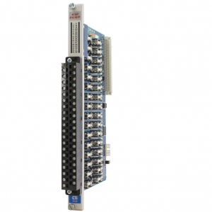
2599
Features
• 8. 16. or 32 AC output points
• Replaces Siemens® 505-4608. -4616. -4632.
-4808. -4816. -4832
• 3000 VDC group-to-group isolation
• 2100 VDC channel-to-backplane isolation
• Isolation in groups of 4 or 8 (selectable with
32 pt login configuration)
• Wide 11-240 VAC output range
• 2.0A per output (32 Amps total module output)
• Individually fused outputs
• Sourcing outputs
• Single-wide module
2599 8/16/32-Point
AC Discrete Output Module
32 Pt Mode: 8 Common Configuration
The module can also be configured so that eight channels share a common user power. The same jumpers
mentioned above, J2. J4. J5. and J6. are used for this selection. In this example, if jumper J2 was placed in the 8 Com
mon position, then Channels 1-8 would share the same common user power and only one supply voltage could be used
on these eight channels. With this selection each group of eight channels is isolated from the other, allowing up to four
different supply voltages to be accommodated per module. The module ships in this configuration.
32-Point Mode: 4 Common Configuration
The user may configure the module to allow four channels to be grouped and share a common field user power, thereby
allowing a different user power supply voltage to be used by each grouping. Jumpers J2. J4. J5. and J6 are used to con
figure this selection. For example, if the user places the J2 jumper in the 4 Common position, Channels 1-4 will share a
common user power and Channels 5-8 will share another common user power. In this example each group of four chan
nels is isolated from the other group of four channels. Because each group of four is isolated, the user may also change
the supply voltage for each group. So, in this example, Channels 1-4 could be 240VAC outputs and Channels 5-8 could
be 120VAC outputs. Furthermore, the user may select a different configuration for J4. J5. or J6. allowing for further com
binations of four or eight channels that share a common.
16 Point Mode:
Move jumper in “Login” box to location JP2 to choose 16pt mode. Ensure the Isolation jumpers J2.4.5. & 6 are in ‘8
Common’ positions to correspond to the Siemens® counterpart 16 point modules (4 inputs/common).
Also, note that many of the printed channels (CH1-CH 32) on the PC board are no longer valid, nor are the front panel
connector labels. (You may find it helpful to utilize the appropriate 16 pt. connector labels shipped with the product.) If
16 Point is enabled, the following table’s 16pt. row is the new correlation of PC board printing and front panel label’s
LED area printing. For example, in 16 Point Login Configuration, the board marking for channel 10 (CH 10) would be the
input channel 6. Likewise, the PC board marking for CH 28 would correlate to input channel 16.
8 Point Mode:
Move jumper in “Login” box to location JP3 to choose 8pt mode. Ensure the Isolation jumpers J2.4.5. & 6 are in ‘8 Com
mon’ positions to correspond to the Siemens® counterpart 8 point modules (2 inputs/common). Also, note that many of
the printed channels (CH1-CH 32) on the PC board are no longer valid, nor are the front panel connector labels. (You
may find it helpful to utilize the appropriate 8 pt. connector labels shipped with the product.) If 8 Point is
enabled, the following table’s 8pt. row is the new correlation of PC board printing and front panel label’s LED area print
ing. For example, in 8 Point Login Configuration, the board marking for channel 10 (CH 10) would be the input channel
4. Likewise, the PC board marking for CH 25 would correlate to input channel 7.