

Hirschmann OZD GENIUS G12 Industrial Switche
The Hirschmann OZD GENIUS G12 (Belden Part Number: 943 881-321) is a specialized industrial fiber optic repeater designed exclusively for legacy Genius Bus fieldbus networks.
By converting electrical Genius Bus signals into optical signals, this module allows industrial plants to extend network distances, eliminate ground loops, and guarantee interference-free data transmission in high-noise environments.
Product Introduction / Overview
In heavy manufacturing plants utilizing GE Fanuc or legacy Emerson control systems, the Genius Bus network is a critical link for distributed I/O. However, long-distance copper fieldbus runs frequently encounter severe electromagnetic interference (EMI) and differences in ground potential between building complexes.
The OZD GENIUS G12 solves this by acting as an active media converter. It features one electrical channel (via a specialized screw terminal block) and two optical channels (BFOC/ST glass fiber ports).
This design enables engineers to transition from traditional line topologies to highly reliable, noise-immune optical ring, star, or redundant-line architectures extending up to 3.000 meters per segment.
Technical Table
| Specification / Parameter | Details |
| Model Code | OZD GENIUS G12 |
| Belden Order Code | 943 881-321 |
| Protocol Support | GE Fanuc Genius Bus / Fieldbus |
| Electrical Interface (CH1) | 4-pin screw terminal block |
| Optical Interfaces | 2 x Optical Channels (CH2 and CH3) utilizing BFOC/ST 2.5 bayonet connectors |
| Fiber Core Compatibility | Multi-mode glass fiber ($50/125\ \mu\text{m}$ or $62.5/125\ \mu\text{m}$) |
| Optical Transmission Distance | Up to 3,000 m per optical segment (depending on fiber quality) |
| Baud Rate Support | Standard Genius Bus speeds: 153.6 kbit/s, 76.8 kbit/s, and 38.4 kbit/s (switch selectable) |
| Optical Wavelength | 850 nm |
| Operating Voltage | Dual redundant $24\text{ V DC}$ inputs ($18\text{ V}$ to $32\text{ V DC}$) |
| Dimensions (W x H x D) | $40\text{ mm} \times 111\text{ mm} \times 115\text{ mm}$ (Slim-profile footprint) |
| Weight | Approximately 500 g |
Environmental Tolerance Conditions
Designed to thrive directly in non-climate-controlled factory environments:
Operating Temperature Range: $0^\circ\text{C}$ to $+60^\circ\text{C}$ ($32^\circ\text{F}$ to $140^\circ\text{F}$)
Storage Temperature Range: $-40^\circ\text{C}$ to $+70^\circ\text{C}$
Relative Humidity: 10% to 95% (completely non-condensing)
Ingress Protection Rating: IP20 (housed in a rugged, passive-cooling metal enclosure)
Conformity Certifications: CE, FCC, industrial safety standards for control equipment
Operating Instructions
1. Pin Assignment & Electrical Connection (CH1)
Wiring the Genius Bus cable to the terminal block must follow the protocol’s standard practices:
Serial 1 (S1): Terminal 1
Serial 2 (S2): Terminal 2
Shield In: Terminal 3
Shield Out: Terminal 4
Important: Always terminate the end-of-line electrical segments of your Genius Bus network with the appropriate external termination resistor (typically 75 $\Omega$, 100 $\Omega$, or 150 $\Omega$ depending on the cable type and baud rate).
2. DIP-Switch Configurations
Prior to powering the device, use the 8-pole front-panel DIP switch to configure the module:
Switches 1–3 (Baud Rate): Manually match the Genius Bus speed running on your controller (e.g., 153.6 kbps).
Switches 4–6 (Topology): Set the module’s behavior based on whether it is operating in a Line, Star, or Redundant Optical Ring structure.
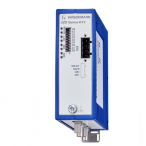
OZD GENIUS G12
Fault Diagnosis
“System” LED is Red or Off:
Cause: Loss of both redundant power supplies or an internal hardware failure.
Remedy: Use a multimeter to verify $24\text{ V DC}$ voltage across both power terminal inputs. Ensure at least one supply is consistently active.
“CH1” LED is Flashing Red:
Cause: No electrical signal detected on the Genius Bus copper interface, or incorrect baud rate set on the DIP switches.
Remedy: Check for loose wires on the terminal block, verify that your master controller is actively polling, and double-check your DIP-switch speed selections.
“CH2” / “CH3” LED is Solid Red:
Cause: The optical signal from the receiving fiber is too weak, completely missing, or Tx/Rx lines are swapped.
Remedy: Verify that Tx on the remote device is connected to Rx on the local device. Measure the receiver level using the integrated front test sockets (healthy levels should read $>1.0\ \text{V}$).
Installation Method
[DIN Rail Upper Groove]
||
\/
====|==== <– Slide upper hook onto standard 35mm rail
|
[ OZD ]
|
====|==== <– Push bottom in until the metal tension spring snaps
Mounting: Hang the upper notch of the DIN-rail slot on the back of the OZD Genius housing onto the top of a standard 35 mm DIN rail (EN 50022).
Locking: Swing the bottom of the device toward the rail until the metal tension spring snaps firmly into place.
Earthing: Securely connect the ground terminal screw at the bottom-front edge of the aluminum housing to the cabinet’s protective earth (PE) busbar to shield sensitive optical circuitry from electromagnetic transients.
Related Models of the Same Series
The Hirschmann OZD fieldbus repeater series features variations tailored to specific industrial bus protocols:
OZD Profi 12M G12: Engineered for high-speed PROFIBUS-DP networks up to 12 Mbit/s.
OZD Modbus G12: Tailored for standard Modbus Plus (RS-485) network conversion.
OZD FMS G12: Designed for older FMS-based fieldbus topologies.
Storage Conditions
Store the device inside its original moisture-resistant packaging in a dry, dust-free environment.
Storage Temperature Limit: $-40^\circ\text{C}$ to $+70^\circ\text{C}$.
Always keep the protective black rubber dust caps inserted over the BFOC optical ports to prevent dust particles or humidity from contaminating the high-sensitivity receiver lenses.