HIRSCHMANN RS20-0800M2M2SDAE Industrial Ethernet Rail Switch
HIRSCHMANN RS20-0800M2M2SDAE Industrial Ethernet Rail Switch
The devices differ with regard to the number of interfaces and the media type
for connecting segments.
There is a variant of the device with 4 ports available, and a variant with 8
ports. The table below shows the number and type of the ports you can
choose. In the column for the port type, the abbreviations F/O (optical fiber)
and TP (twisted pair) indicate the media type, while the abbreviations DSC
and RJ45 indicate the socket type.
1.1.1 Combination options for RS20-…B
The product designation of your device is made from combining the desired
product characteristics in accordance with the following table. The
corresponding short designation is in column 3.
Item Characteristic Ident. Property
1 to 4 Product RS20 Rail Switch without gigabit ports
5- (hyphen)
6 to 7 Number of 10/100 04 4 * 10/100 Mbit/s Ethernet
Mbit/s ports 08 8 * 10/100 Mbit/s Ethernet
8 and 9 Number of 1000
Mbit/s ports
00 0 * 1000 Mbit/s Ethernet
10 and 11 Uplink port 1 T1 Twisted pair T(X), RJ45
M2 Multimode FX, DSC, 100 Mbit/s
12 and 13 Uplink port 2. see
items 10 and 11
RS20-0800M2M2SDAE
14 Temperature range S Standard 0 °C to +60 °C
15 Voltage range D 9.6 VDC to 60 VDC or 18 VAC to 30 VAC
16 Certification A CE, UL 508. ISA 12.12.01 (UL 1604)
17 Software variant B Basic
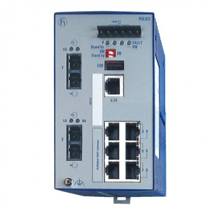
Device variants with 4 * 10/100 Mbit/s ports (RS20-0400…B)
1 – plug-in terminal block, 6-pin
2 – LED display elements
3 – V.24 connection for external management
4 – ports in compliance with 10/100BASE-T(X) (RJ45 connections)
5 – port 1 + port 2. free choice of connections:
T1: Twisted-pair T(X), RJ45. 10/100 Mbit/s
M2: Multimode FX, DSC, 100 Mbit/s
6 – MAC address field
7 – IP address field
Assembly and start-up
The devices have been developed for practical application in a harsh
industrial environment.
On delivery, the device is ready for operation.
The following steps should be performed to install and configure a switch:
Unpacking and checking
Insert data in label area
Connect the terminal block for voltage supply and signal
contact and connect the supply voltage
Install the device on the DIN rail, grounding
Install the terminal block, start-up procedure
Connecting the data lines