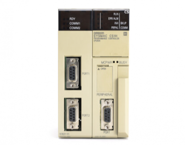
OMRON CS1H-CPU63-EV1 PLC
OMRON CS1H-CPU63-EV1 PLC
Item Specifications
EM Area
32K words per bank, 13 banks max.: E0_00000 to EC_32767 max. (Varies by CPU Unit model.)
Used as a general-purpose data area for reading and writing data in word units (16 bits). Words in the EM Area maintain their status when
the PLC is turned OFF or the operating mode is changed.
The EM Area is divided into banks, and the addresses can be set by either of the following methods.
Changing the current bank using the EMBC(281) instruction and setting addresses for the current bank. Setting bank numbers and
addresses directly.
EM data can be stored in files by specifying the number of the first bank.
Data Registers DR0 to DR15: Store offset values for indirect addressing. One register is 16 bits (1 word).
Index Registers IR0 to IR15: Store PLC memory addresses for indirect addressing. One register is 32 bits (2 words).
Task Flag Area 32 (TK0000 to TK0031): Task Flags are read-only flags that are ON when the corresponding cyclic task is executable and OFF when the
corresponding task is not executable or in standby status.
Trace Memory 4.000 words (The maximum amount of data that can be traced in a data trace is 500 samples for 31 bits and 6 words.
File Memory Memory Cards: Compact flash memory cards can be used (MS-DOS format).
EM file memory: Part of the EM Area can be converted to file memory (MS-DOS format).
Functions
Parallel Processing
Modes Program execution and peripheral servicing can be performed simultaneously.
Battery-free operation The user program and the system’s parameters are backed up automatically in flash memory, which is standard equipment.
Constant cycle time Possible (1 to 32.000 ms) (Unit: 1 ms)
Cycle time monitoring Possible (Unit stops operating if the cycle is too long): 10 to 40.000 ms (Unit: 10 ms)
I/O refreshing Cyclic refreshing, immediate refreshing, refreshing with I/O REFRESH instruction
I/O memory holding
when changing
operating modes
Possible (Depends on the ON/OFF status of the IOM Hold Bit in the Auxiliary Area.)
Load OFF All outputs on Output Units can be turned OFF.
Input response time
setting
Time constants can be set for inputs from Basic I/O Units.
The time constant can be increased to reduce the influence of noise and chattering or it can be decreased to detect shorter pulses on the
inputs (CS1 Basic I/O Units only).
Startup mode setting Supported.
Memory Card
functions
Automatically reading programs (autoboot) from the Memory Card when the power is turned ON.
Format in which data is stored in Memory Card
User program: Program file format
PLC Setup and other parameters: Data file format (binary format)
I/O memory: Data file format (binary format), text format, or CSV format
Functions for which Memory Card read/write is
supported
User program instructions, Programming Devices (including Programming Consoles),
Host Link computers
Filing Memory Card data and the EM (Extended Data Memory) Area can be handled as files.
Debugging Control set/reset, differential monitoring, data tracing (scheduled, each cycle, or when instruction is executed), storing location generating
error when a program error occurs
Online editing User programs can be overwritten in program-block units when the CPU Unit is in MONITOR or PROGRAM mode.
(This function is not available for block programming areas.)
Program protection Overwrite protection: Set using DIP switch.
Copy protection: Password set using Programming Device.
Error check User-defined errors (i.e., user can define fatal errors and non-fatal errors)
The FPD(269) instruction can be used to check the execution time and logic of each programming block.
Error log Up to 20 errors are stored in the error log. Information includes the error code, error details, and the time the error occurred.
Serial
communications
Built-in peripheral port: Programming Device (including Programming Console) connections, Host Links, NT Links
Built-in RS-232C port: Programming Device (excluding Programming Console) connections, Host Links, no-protocol communications, NT
Links, and Serial Gateway *3
Serial communications board (order separately): protocol macros, Host Links, no-protocol communications *3. NT Links, Serial Gateway
*3. and Modbus-RTU Slave *5
Clock Provided on all models.
Note: Used to store the time when power is turned ON and when errors occur.
Power OFF detection
time 10 to 25 ms (not fixed)
Power OFF detection
delay time 0 to 10 ms (user-defined, default: 0 ms)
Memory retention
during power
interruptions
Held Areas: Holding bits, contents of Data Memory and Extended Data Memory, and status of the counter Completion Flags and present
values.
Note: If the IOM Hold Bit in the Auxiliary Area is turned ON, and the PLC Setup is set to maintain the IOM Hold Bit status when power to
the PLC is turned ON, the contents of the CIO Area, the Work Area, part of the Auxiliary Area, timer Completion Flags and PVs, Index
Registers, and the Data Registers will be saved.
Sending commands to
a Host Link comput
CS1H-CPU63-EV1