

CTI 2500-ADP1 Analog Wiring Adapter for Series 500
2500-ADP1 Analog Wiring Adapter for Series 500
The 2500-ADP1 is a wiring adapter which converts analog field wiring from Series 500 base format to the 40-pin connector used on CTI 2500 Series® analog I/O modules.
This allows rapid upgrade of existing Series 500 systems to newer and more supportable 2500 Series®.
It provides a transparent path for upgrading old Series 500 systems without the requirement to completely replace the system.
Features
Converts 500-5037A 8ch Analog In connector to a CTI 2558 8ch Analog In 40F connector
Converts 500-5047A 8ch Analog Out connector to a CTI 2562 8ch Analog Out 40F connector
Allows easy replacement of failed Series 500 analog I/O modules with inexpensive and widely available CTI 2500 Series® analog modules
Allows you to plan system upgrade according to your budget
Preserves your investment in replacement modules
Instructions
Classic
Method A – Installing the new module into an I/O
adapter in the existing Series 500 base
1. Remove power from the Series 500 base.
2. Remove the 500-5037A/47A to be upgraded.
3. Install the 2500-IADP in the slot where the 500
module was removed.
4. Configure the 2558 / 2562 to match the 500
module to be replaced.
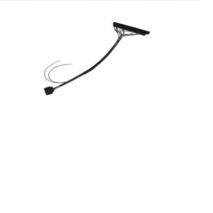
2500-ADP1
Description
The 2500-ADP1 is a wiring adapter which converts
analog field wiring from Series 500 base format to the
40-pin connector used on CTI 2500 Series® analog I/O
modules. This allows rapid upgrade of existing Series
500 systems to newer and more supportable 2500
Series®
Features
The 2500-ADP1 cable converts the following Field
wiring:
• 500-5037A 8ch Analog In connector to a CTI 2558
8ch Analog In 40F connector
• 500-5047A 8ch Analog Out connector to a CTI
2562 8ch Analog Out 40F connector
5. Install the 2558 / 2562 into the 2500-IADP.
6. Connect the Edge card connector of the 2500
ADP1 into the existing 5037A / 5047A field wiring
connector (The silkscreen labeling on the Edge
Card connector shows pin 1 and pin A. This should
line up with pin 1 and pin A of the Field wiring
connector).
7. Remove any 250 Ohm current resistors that may
be installed in the 5037A / 5047A field wiring
connector. They are not needed on the 2558 /
2562.
8. Connect the 40F connector to the 2558 / 2562.
9. Return power to the rack. analog input channels.
Method B – Installing the new module into a new
2500 Series® base
1. Remove power from the Series 500 base.
2. Remove the 500-5037A/47A to be upgraded.
3. Configure the 2558 / 2562 to match the 500
module to be replaced.
4. Install the 2558 / 2562 into the 2500 SeriesTM
base.
5. Connect the Edge card connector of the 2500
ADP1 into the existing 5037A / 5047A field wiring
connector (The silkscreen labeling on the Edge
Card connector shows pin 1 and pin A. This should
line up with pin 1 and pin A of the Field wiring
connector).
6. Remove any 250 Ohm current resistors that may
be installed in the 5037A / 5047A field wiring
connector. They are not needed on the 2558 /
2562.
7. Connect the 40F connector to the 2558 / 2562.
8. Return power to the rack.