

VIBRO-METER IOC4T 200-560-000-113 I/O interface card
VIBRO-METER IOC4T 200-560-000-113 I/O interface card
IOC4T input/output card (ABE04x and ABE056)
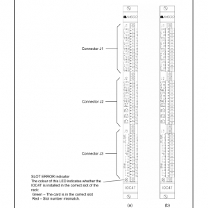
The IOC4T panel (rear of rack) contains three terminal strips, identified as J1. J2 and J3
(seeFigure2-9). Each strip consists of a socket and a mating connector, which contains 16
screw terminals. The screw terminals can accept wires with a cross-section of ≤1.5mm2.
Figure2-9(a) shows the appearance of the IOC4T panel without the three mating
connectors. In this configuration, the engraving showing the terminal definitions is clearly
seen. Figure2-9(b) shows the appearance of the panel when the 3 mating connectors are
inserted.
DIAG/STATUS indicator for the MPC4/ IOC4T card pair.
The colours of the LED have the following significance:
* Green(continuous) – Normal operation (configuration valid with no active
alarms and no errors).
* Green blinking – Configuration is being downloaded (stabilisation phase)
and/or signal processing error.
* Yellow(continuous) – Trip Multiply (TM) function active.
* Yellow blinking – Configuration error and/or signal processing error.
* Red(continuous) – Danger Bypass (DB) function active.
* Red blinking – Hardware or input erro
Status indicator for the MPC4/ IOC4T card pair measurement channel1.
The colours of the LED have the following significance:
* Off – Channel not configured (“Sensor Connected” set to “No” in
the VM600 MPSx software) or card not configured.
* Green(continuous) – Signal input to the channel is valid and there are
no active alarms.
* Green blinking – Signal input to the channel is not valid.
* Green blinking slowly – Channel inhibit function active.
* Yellow(continuous) – There is an active single-channel processing
Alert level alarm ((A−) or (A+)).
* Yellow blinking – There is an active dual-channel processing
Alert level alarm ((A−) or (A+)). Note: The status indicator LED for both
channels will blink yellow at the same time.
* Red(continuous) – There is an active single-channel processing
Danger level alarm ((D−) or (D+)).
* Red blinking – There is an active dual-channel processing
Danger level alarm ((D−) or (D+)). Note: The status indicator LED for both
channels will blink red at the same time
Status indicator for the MPC4/ IOC4T card pair rotational speed channel1
(TACHO1).
IOC4T
The colours of the LED have the following significance:
* Off – Channel not configured (“Sensor Connected” set to “No” in.
the VM600 MPSx software)
* Green(continuous) – Signal input to the channel is valid and there are
no active alarms.
* Green blinking – Signal input to the channel is not valid.
* Green blinking slowly – Channel inhibit function active.
* Yellow(continuous) – There is an active single-channel processing
Alert level alarm ((A−) or (A+)).
Status indicator and BNC connector for the MPC4/IOC4T card pair rotational
speed channel2 (TACHO2).
Operation as per speed channel1 (TACHO1)
BNC connector for the
MPC4/ IOC4T card pair
measurement channel1.
Raw signal output.
Transfer function:
Voltage input: 1V/V
Current input: 0.3245 V/mA.
Status indicator and BNC
connector for the
MPC4/IOC4T card pair
measurement channels2. 3
and 4.
Operation as per
measurement channel1.
BNC connector for the
MPC4/ IOC4T card pair
rotational speed channel1
(TACHO1).
Raw signal output (TTL
compatible
RS-232 connector.
Can be used to configure an
MPC4 card in a stand-alone
rack (without CPUM card)
using the VM600 MPSx
software.
Note: The safety version of
the MPC4 card (MPC4SIL)
does not have a VME bus
interface so it can only be
configured via this serial link
(even in a networked VM600
rack).