

Basler Electric, Solid State Protective Relay, BE1-60
Basler Electric, Solid State Protective Relay, BE1-60
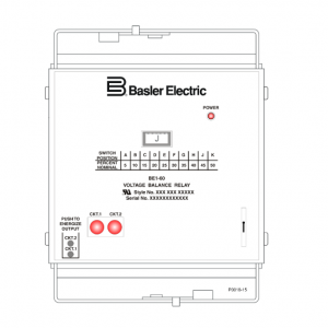
The BE1-60 Voltage Balance Relay provides a high-speed response to block other devices from incorrect
operation resulting from a blown fuse or other fault in a potential transformer circuit. The BE1-60 detects
these conditions, initiates corrective action, and indicates the problem and location.
Equipment benefiting from BE1-60 protection includes overcurrent relays (voltage-controlled or voltage
restrained types), impedance-measuring relays, synchronizing relays, voltage regulators, and static
excitation systems.
In the typical application shown in Figure 1-1. a generator is equipped with a static exciter and is
protected by voltage controlled or voltage restrained time-overcurrent relays and other devices.
If a power potential transformer fuse opens, the resulting unbalanced condition may cause excessive
heating in the power stage of the static exciter. This condition would warrant an alarm indication and an
orderly shutdown of the unit. The BE1-60 Circuit 1 output would accomplish this task and the Circuit 1
target would indicate that an open power potential transformer fuse had initiated the correct shutdown
sequence.
If a sensing potential transformer fuse opens, the static exciter (with three-phase sensing) output would
increase to maximum in an attempt to restore the sensed voltage to the proper level. For this condition,
the BE1-60 would initiate an emergency shutdown of the unit and issue an alarm. The BE1-60 Circuit 2
output would accomplish this task and the Circuit 2 target would indicate that an open sensing potential
transformer fuse had initiated the correct shutdown sequence.
In addition, since the same potential source provides the control1 or restraint2 input to the time
overcurrent relays, false tripping of the unit may result due to operation of the overcurrent relays. This is
undesirable because the overcurrent relay target would give a false indication of the reason for tripping.
To prevent this, the BE1-60 Circuit 2 output would be required to block operation of the overcurrent
relays. This would be accomplished by opening a normally-closed contact from the BE1-60. which is in
series with the tripping outputs of the overcurrent relays.
1If the overcurrent functions were voltage controlled and the output current exceeded the relay
pickup setting, a loss of power potential would allow this overcurrent function to pick up and start
timing. Without the inhibit from the BE1-60. tripping would result.
2If the overcurrent functions were voltage restrained, the loss of restraint potential would increase
the sensitivity of the relay (2½ times setting) and the relay would pick up and start timing. Without
the inhibit from the BE1-60. tripping would result.
Setting the Relay
When setting the relay, consideration should be given to the maximum voltage excursions permitted for
normal operating conditions. For example, if the power potential transformer output varies 5% from
machine no-load to machine full-load, the setting must accommodate this fluctuation.
Also, note that since both BE1-60 inputs (Circuit 1 and Circuit 2) are monitoring essentially the same
voltage, BE1-60 tripping will not occur for system faults.
BE1-60 relays with sensing input type E (single-phase to three-phase wye) or F (single-phase to three
phase delta) apply the three-phase input to an internal, Scott (T-connected) transformer. This transformer
produces a single-phase voltage that is proportional to the average of the three-phase voltages shown in
Figure 1-2. This decreases the relay’s sensitivity as illustrated by the following example.
Setting Example for Sensing Input Types E and F
CIRCUIT 2
BE1-60
INPUT
If a fuse blows in phase C of Circuit 2. an apparent difference of 40 volts is produced within the relay.
Since Circuit 1 is nominally rated at 120 Vac, the three-phase voltages of Circuit 2 are defined as line-to
neutral for a type E wye input or line-to-line for a type F delta input. This apparent voltage difference is not
sufficient to produce a response if the pickup setting is G, H, J, or K since these settings represent
voltage differences of 42. 48. 54. and 60 volts respectively. Therefore, it is recommended that the lower
pickup settings be used for relays with sensing input styles E or F.
Operative Example
The following example details the effect that the BE1-60 would have on the system shown in Figure 1-1.
Given: Potential transformer secondary voltages are 120 Vac
BE1-51/27R pickup setting is 4.5 Aac
BE1-60 pickup setting is B (10%)
Assume that a fault causes the sensing potential transformer secondary voltage to dip 9% to 109.2 Vac.
Characteristically, the BE1-51/27R will pickup and start timing when the line current reaches 4.095 Aac
(instead of 4.5 Aac) as determined below.
A 4.095 (91%) A 4.5 9%) (100% A 4.5 = = −
This will result in the BE1-51/27R producing an undesired trip. The trip is undesired because the current
pickup level has been inadvertently lowered by the voltage dip seen on the secondary winding of the
sensing transformer—even though the line voltage has not changed.
Now assume that the fault causes the sensing potential transformer secondary voltage to dip 10% to 108
Vac. This will cause the BE1-51/27R to pick up and start timing at 4.05 Aac as shown below.
A 4.05 (90%) A 4.5 10%) (100% A 4.5 = = −
However, since the voltage dip seen on the secondary winding of the sensing potential transformer meets
the 10% pickup setting of the BE1-60 and the secondary voltage of the power potential transformer has
not changed, any undesired trip signal from the BE1-51/27R will be blocked by the BE1-60 Circuit 2
output contacts.
Model and Style Number
The electrical characteristics and operational features of the BE1-60 relay are defined by the model
number and style number. The model and style numbers appear on the relay front panel, draw-out cradle,
and inside the case. The model number BE1-60 identifies the relay as a Basler Electric Class 100 Voltage
Balance Relay. The style identification chart for the BE1-60 relay is shown in Figure 1-3.
Sample Style Number
The style number identification chart of Figure 1-3 illustrates how the BE1-60 relay’s operating
characteristics are determined. For example, if the style number were D1H-A1R-C0C2F, the BE1-60 relay
would have the following features.
D three-phase wye to three-phase delta sensing input
1 sensing range of 60 to 125% of nominal
H two normally-closed output relays (one per monitored circuit)
A1 instantaneous timing
R operating power derived from 24 Vdc source
C two internally operated targets (one per circuit)
0 no power supply status output
C push-to-test outputs (pushbuttons)
2 normally-closed auxiliary output contacts (one per circuit)
F ———- semi-flush case mounting