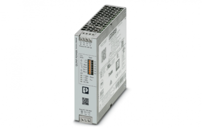
Phoenix 2904600 QUINT4-PS/1AC/24DC/5 – Power supply
QUINT4-PS/1AC/24DC/5 – Power supply
2904600
2904600
The fourth generation of the high-performance QUINT POWER power supplies ensures superior system availability by means of new functions.
Signaling thresholds and characteristic curves can be individually adjusted via the NFC interface.
The unique SFB technology and preventive function monitoring of the QUINT POWER power supply increase the availability of your application
Control input (configurable) Rem Output power ON/OFF (SLEEP MODE)
Default Output power ON (>40 kΩ/24 V DC/open bridge between Rem and SGnd)
AC operation
Supply system configuration Star network
Nominal input voltage range 100 V AC … 240 V AC
Input voltage range 100 V AC … 240 V AC -15 % … +10 %
Derating < 100 V AC (1 %/V)
Electric strength, max. 300 V AC 60 s
Typical national grid voltage 120 V AC
230 V AC
Voltage type of supply voltage AC
Inrush current typ. 14 A (at 25 °C)
Inrush current integral (I2t) < 0.3 A2s
Inrush current limitation 14 A (after 1 ms)
AC frequency range 50 Hz … 60 Hz -10 % … +10 %
Frequency range (fN) 50 Hz … 60 Hz -10 % … +10 %
16.7 Hz (acc. to EN 50163)
Mains buffering time typ. 28 ms (120 V AC)
typ. 38 ms (230 V AC)
Current consumption 1.7 A (100 V AC)
1.5 A (120 V AC)
0.9 A (230 V AC)
0.8 A (240 V AC)
Nominal power consumption 163 VA
Protective circuit Transient surge protection; Varistor, gas-filled surge arrester
Power factor (cos phi) 0.82
Switch-on time < 500 ms
Typical response time 300 ms (from SLEEP MODE)
Input fuse 6.3 A (slow-blow, internal)
Recommended breaker for input protection 6 A … 16 A (Characteristic B, C, D, K or comparable)
Discharge current to PE < 3.5 mA
1.1 mA (264 V AC, 60 Hz)
DC operation
Nominal input voltage range 110 V DC … 250 V DC
Input voltage range 110 V DC … 250 V DC -18 % … +40 %
Derating < 110 V DC (1 %/V)
Voltage type of supply voltage DC
Current consumption 1.6 A (110 V DC)
0.7 A (250 V DC)
Efficiency typ. 88.8 % (120 V AC)
typ. 89.2 % (230 V AC)
Output characteristic U/I Advanced
Smart HICCUP
FUSE MODE
Nominal output voltage 24 V DC
Setting range of the output voltage (USet) 24 V DC … 29.5 V DC (constant capacity)
Nominal output current (IN) 5 A
Static Boost (IStat.Boost) 6.25 A
Dynamic Boost (IDyn.Boost) 10 A (5 s)
Selective Fuse Breaking (ISFB) 30 A (15 ms)
Magnetic circuit breaker tripping A1 … A4 / B2 / C1 … C2 / Z1 … Z4
Derating > 60 °C … 70 °C (2.5 %/K)
Feedback voltage resistance ≤ 35 V DC
Protection against overvoltage at the output (OVP) ≤ 32 V DC
Control deviation < 0.5 % (Static load change 10 % … 90 %)
< 4 % (Dynamic load change 10 % … 90 %, (10 Hz))
< 0.25 % (change in input voltage ±10 %)
Residual ripple < 30 mVPP (with nominal values)
Short-circuit-proof yes
No-load proof yes
Output power 120 W
150 W
240 W
Apparent power 180 VA (120 V, UOUT = 24 V, IOUT = stat. Boost)
198 VA (230 V, UOUT = 24 V, IOUT = stat. Boost)
Maximum no-load power dissipation < 3 W (120 V AC)
< 3 W (230 V AC)
Power loss nominal load max. < 17 W (120 V AC)
< 16 W (230 V AC)
Power dissipation SLEEP MODE < 3 W (120 V AC)
< 3 W (230 V AC)
Crest factor typ. 1.55 (120 V AC)
typ. 1.78 (230 V AC)
Rise time 50 ms (UOut = 10 % … 90 %)
Connection in parallel yes, for redundancy and increased capacity
Connection in series yes
Fuse protection (secondary side) electronic
thermal-magnetic
thermal
Signal
Signal ground SGnd Reference potential for Out1. Out2. and Rem
Signal Out 1 (configurable)
Digital 24 V DC 20 mA
Default 24 V DC 20 mA 24 V DC for UOut > 0.9 x USet
Signal Out 2 (configurable)
Digital 24 V DC 20 mA
Analog 4 mA … 20 mA ±5 % (Load ≤400 Ω)
Default 24 V DC 20 mA 24 V DC for POut < PN
Signal relay 13/14 (configurable)
Default closed (Uout > 0.9 USet)
Digital 24 V DC 1 A
30 V AC/DC 0.5 A
Connection method Screw connection
Conductor cross-section, rigid min. 0.2 mm²
Conductor cross-section, rigid max. 2.5 mm²
Conductor cross-section flexible min. 0.2 mm²
Conductor cross-section flexible max. 2.5 mm²
Single conductor/flexible terminal point with ferrule with plastic sleeve, min. 0.25 mm²
Single conductor/flexible terminal point with ferrule with plastic sleeve, max. 2.5 mm²
Single conductor/flexible terminal point with ferrule without plastic sleeve, min. 0.25 mm²
Single conductor/flexible terminal point with ferrule without plastic sleeve, max. 2.5 mm²
Conductor cross-section AWG min. 24
Conductor cross-section AWG max. 14
Stripping length 6.5 mm
Tightening torque, min 0.5 Nm
Tightening torque max 0.6 Nm
Output
Connection method Screw connection
Conductor cross-section, rigid min. 0.2 mm²
Conductor cross-section, rigid max. 2.5 mm²
Conductor cross-section flexible min. 0.2 mm²
Conductor cross-section flexible max. 2.5 mm²
Single conductor/flexible terminal point with ferrule with plastic sleeve, min. 0.25 mm²
Single conductor/flexible terminal point with ferrule with plastic sleeve, max. 2.5 mm²
Single conductor/flexible terminal point with ferrule without plastic sleeve, min. 0.25 mm²
Single conductor/flexible terminal point with ferrule without plastic sleeve, max. 2.5 mm²
Conductor cross-section AWG min. 24
Conductor cross-section AWG max. 14
Stripping length 6.5 mm
Tightening torque, min 0.5 Nm
Tightening torque max 0.6 Nm
Signal
Connection method Push-in connection
Conductor cross-section, rigid min. 0.2 mm²
Conductor cross-section, rigid max. 1 mm²
Conductor cross-section flexible min. 0.2 mm²
Conductor cross-section flexible max. 1.5 mm²
Single conductor/flexible terminal point with ferrule with plastic sleeve, min. 0.2 mm²
Single conductor/flexible terminal point with ferrule with plastic sleeve, max. 0.75 mm²
Single conductor/flexible terminal point with ferrule without plastic sleeve, min. 0.2 mm²
Single conductor/flexible terminal point with ferrule without plastic sleeve, max. 1.5 mm²
Conductor cross-section AWG min. 24
Conductor cross-section AWG max. 16
Stripping length 8 mm
Types of signaling LED
Floating signal contact
Active signal output Out1 (digital, configurable)
Active signal output Out2 (analog, configurable)
Remote contact
Signal ground SGnd
Signal output
Signal option Output current
Output voltage
Output power
UIN input voltage OK
Operating hours
Early warning of high temperatures
OVP voltage limitation active
POut > 100 % (LED lights up yellow, output power > 120 W)
> 75 % (LED lights up green, output power > 90 W)
> 50 % (LED lights up green, output power > 60 W)
UOut > 0.9 x USet (LED lights up green)
< 0.9 x USet (LED flashes green
CSA CAN/CSA-C22.2 No. 60950-1-07
CSA-C22.2 No. 107.1-01
Shipbuilding approval DNV GL, PRS, BV, LR, ABS
SIQ BG (type approved)
UL approvals UL Listed UL 508
UL/C-UL Recognized UL 60950-1
UL ANSI/ISA-12.12.01 Class I, Division 2. Groups A, B, C, D T4 (Hazardous Location)
| MOLEX | 85003-0567 |
| MOOG | T161-902A-00-B4-2-2A |
| MOOG | M128-010 |
| MOOG | G123-825-001 |
| MOOG | D136-001-007 |
| MOOG | D138-002-001 |
| MOOG | D138-002-002 |
| MOOG | D136-001-008 |
| MOOG | D136-001-008a |
| MOOG | M128-010 M128-010-A001B |
| MOOG | D136-002-005 |
| MOOG | D136E001-001 |
| MOOG | D136-001-001 |
| MOOG | D136-002-002 |
| MOOG | QAIO2/2-AV D137-001-011 |