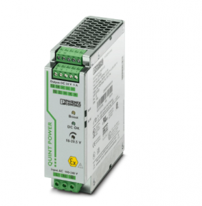
Phoenix 2320908 QUINT-PS/1AC/24DC/ 5/CO – Power supply, with protective coating
QUINT-PS/1AC/24DC/ 5/CO – Power supply, with protective coating
2320908
Primary-switched power supply unit QUINT POWER, Screw connection, DIN rail mounting, SFB Technology (Selective Fuse Breaking),
input: 1-phase, output: 24 V DC / 5 A, adjustable from 18 V DC … 29.5 V DC
QUINT POWER power supplies with maximum functionality
QUINT POWER circuit breakers magnetically and therefore quickly trip at six times the nominal current, for selective and therefore cost-effective system protection.
In addition, the high system availability is ensured by preventive function monitoring which reports critical operating states before errors can occur.
Reliable starting of heavy loads takes place via the static power reserve POWER BOOST. Thanks to the adjustable voltage, all ranges between 18 V DC … 29.5 V DC are covered.
Nominal input voltage range 100 V AC … 240 V AC
Input voltage range 85 V AC … 264 V AC
Electric strength, max. 300 V AC
Voltage type of supply voltage AC
Inrush current < 15 A
Inrush current integral (I2t) < 1 A2s
Inrush current limitation 15 A
AC frequency range 45 Hz … 65 Hz
Frequency range DC 0 Hz
Mains buffering time typ. 55 ms (120 V AC)
typ. 55 ms (230 V AC)
Current consumption 1.5 A (100 V AC)
0.6 A (240 V AC)
Nominal power consumption 141 VA
Protective circuit Transient surge protection; Varistor
Typical response time < 0.15 s
Input fuse 5 A (slow-blow, internal)
Permissible backup fuse B6 B10 B16 AC:
Recommended breaker for input protection 6 A … 16 A (AC: Characteristics B, C, D, K)
Discharge current to PE < 3.5 mA
DC operation
Nominal input voltage range 110 V DC … 250 V DC
Input voltage range 110 V DC … 250 V DC -18 % … +64 % (UL 508: ≤ 250 V DC)
Voltage type of supply voltage DC
Current consumption 1.3 A (110 V DC)
0.55 A (250 V DC)
Efficiency typ. 88.3 % (120 V AC)
typ. 90 % (230 V AC)
Nominal output voltage 24 V DC ±1 %
Setting range of the output voltage (USet) 18 V DC … 29.5 V DC (> 24 V DC, constant capacity)
Nominal output current (IN) 5 A (-25 °C … 60 °C, UOUT = 24 V DC)
POWER BOOST (IBoost) 7.5 A (-25 °C … 40 °C permanent, UOUT = 24 V DC )
Selective Fuse Breaking (ISFB) 30 A (12 ms)
Magnetic circuit breaker tripping B2 / B4 / C2
Derating 60 °C … 70 °C (2.5 %/K)
Feedback voltage resistance ≤ 35 V DC
Protection against overvoltage at the output (OVP) ≤ 32 V DC
Control deviation < 1 % (change in load, static 10 % … 90 %)
< 2 % (change in load, dynamic 10 % … 90 %)
< 0.1 % (change in input voltage ±10 %)
Residual ripple < 40 mVPP (with nominal values)
Output power 120 W
180 W
QUINT-PS1AC24DC 5CO
Maximum no-load power dissipation 3 W
Power loss nominal load max. 15 W
Rise time < 0.1 s (UOUT (10 % … 90 %))
Connection in parallel yes, for redundancy and increased capacity
Connection in series yes
Fuse protection (secondary side) electronic
thermal-magnetic
thermal
Signal: DC OK active
Output description UOUT > 0.9 x UN: High signal
Switching voltage range 18 V DC … 24 V DC
Maximum inrush current 20 mA (short-circuit-proof)
Continuous load current ≤ 20 mA
Signal: DC OK floating
Output description Relay contact, UOUT > 0.9 x UN: Contact closed
Maximum switching voltage 30 V AC
24 V DC
Maximum inrush current 0.5 A (ATEX/IECEx: Ohmic loads only)
1 A (ATEX/IECEx: Ohmic loads only)
Continuous load current 1 A
Signal: POWER BOOST, active
Output description IOUT < IN: High signal
Switching voltage range 18 V DC … 24 V DC
Output voltage + 24 V DC
Maximum inrush current 20 mA (short-circuit-proof)
Continuous load current ≤ 20 mA
Connection method Screw connection
Conductor cross-section, rigid min. 0.2 mm²
Conductor cross-section, rigid max. 2.5 mm²
Conductor cross-section flexible min. 0.2 mm²
Conductor cross-section flexible max. 2.5 mm²
Conductor cross-section AWG min. 20
Conductor cross-section AWG max. 12
Stripping length 7 mm
Screw thread M3
Tightening torque, min 0.5 Nm
Tightening torque max 0.6 Nm
Output
Connection method Screw connection
Conductor cross-section, rigid min. 0.2 mm²
Conductor cross-section, rigid max. 2.5 mm²
Conductor cross-section flexible min. 0.2 mm²
Conductor cross-section flexible max. 2.5 mm²
Conductor cross-section AWG min. 20
Conductor cross-section AWG max. 12
Stripping length 7 mm
Screw thread M3
Tightening torque, min 0.5 Nm
Tightening torque max 0.6 Nm
Signal
Conductor cross-section, rigid min. 0.2 mm²
Conductor cross-section, rigid max. 2.5 mm²
Conductor cross-section flexible min. 0.2 mm²
Conductor cross-section flexible max. 2.5 mm²
Conductor cross-section AWG min. 20
Conductor cross-section AWG max. 12
Screw thread M3
Tightening torque, min 0.5 Nm
Tightening torque max 0.6 Nm
Types of signaling LED
Active switching output
Relay contact
Signal output: DC OK active
Status display UOUT > 0.9 x UN: “DC OK” LED green
Note on status display UOUT < 0.9 x UN: Flashing “DC OK” LED
IOUT < IN: LED ON
Color green
Note on status display LED flashing
Signal output: DC OK floating
Status display UOUT > 0.9 x UN: “DC OK” LED green
Note on status display UOUT < 0.9 x UN: Flashing “DC OK” LED
Color green
Note on status display LED flashing
Signal output: POWER BOOST, active
Status display IOUT > IN: LED “BOOST” yellow
Color yellow
Number of phases 1
Insulation voltage input/output 4 kV AC (type test)
2 kV AC (routine test)
Insulation voltage output / PE 850 V DC (routine test)
Insulation voltage input / PE 3.5 kV AC (type test)
2 kV AC (routine test)
Product family QUINT POWER
MTBF (IEC 61709. SN 29500) > 1134000 h (25 °C)
> 635000 h (40 °C)
Insulation characteristics
Protection class I
Degree of pollution 2
Width 40 mm
Height 130 mm
Depth 125 mm
Installation dimensions
Installation distance right/left 5 mm / 5 mm
Installation distance top/bottom 50 mm / 50 mm
Alternative assembly
Width 122 mm
Height 130 mm
Depth 43 mm