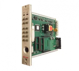
Honeywell 05701-A-0361 Engineering Card
Manufacturer : HONEYWELL
Part Number : 05701-A-0361
Product Type : Engineering Card
Used on a System 57 rack to provide a common interface
Enables the user to perform all the required functions to commission and operate each fitted control card
LEDs : Power On ( – Green LED) | Unlocked ( – Red LED)
Push-Button :
Operating : Up and Down | Reject and Accept | Print (Up and Down together)
Functions :
Bead mA Alarms
Zero Signal
Span 1st Span
Inhibit Clock
Power Consumption : 1.5W (typical)
DC Supply : 18V to 32V dc
Height : 132 mm
Width : 25 mm
Depth : 170 mm
Weight : 152 g
Shipping Weight : 1.5 Kg
05701-A-0361
a single loop of gas detection as follows:
Processes the incoming sensor drive module signal.
Displays the signal level on the front panel liquid crystal display.
Compares the signal level with pre-defined alarm limits.
When the pre-defined alarm limits are exceeded, raises the alarms
by lighting up front panel LEDs and operating optional connected
relays.
Informs other cards with the alarm status information.
Self validates the operation of its circuit components, software
operation and the condition of the sensor.
Sensor Drive Modules
Two sensor drive modules are provided:
Sensor Drive Module, 4 – 20mA, Part Number 05701-A-0283
Sensor Drive Module Catalytic,
Part Number 05701-A-0284
The Sensor Drive Module conditions the incoming catalytic or 4 – 20mA
sensor signal and provides the necessary sensor power supply. It
contains all the circuitry necessary to generate the voltages and currents
required to drive the sensor, the circuitry to acquire the sensor signal
and to scale the sensor signal to a standard output. The sensor drive
modules are factory fitted and plug directly onto the channel control
card.
Analogue Output Module
An optional Analogue Output Module, (Part Number 05701-A-0285),
may be factory fitted to the Single Channel Control Card and is used
on a channel of gas detection to provide an isolated current loop output
which follows the sensor signal level. This may be set electronically to
produce a 0 – 20mA output or a 4 – 20mA output and can be used to
operate a chart recorder, etc.
Single Channel Control Card Physical Layout
The physical layout of the Single Channel Control Card is shown below.
The Sensor Drive Modules plug into the 14-way connectors J1 and
J2 while the Analogue Output Module, when fitted, plugs into J3 and
J4. Link LK1. available on MkII cards only, is used when individually
powering control cards See Chapter 4. Section 16.2
5.1
FIELD INTERFACE AND RELAY CARDS
General
The Field Interface Card and the four types of relay card provide the
interface between a Single Channel Control Card and the field wiring.
5.2
Field Interface Card (Part Number 05701-A-0326)
5.2.1 General
For use in systems with master relays. Used on all channels except
the master. Provides connections between the sensor and the control
card only. No relays fitted.
Double SPCO Relay Card (Part Number 05701-A-0327)
5.3.1 General
Provides connections between the sensor and the control card in
the same way as the Field Interface Card. In addition, single pole
relays provide voltage free contact outputs for the A1 alarm level,
A2 alarm level and fault condition
Triple SPCO Relay Card (Part Number 05701-A-0328)
5.4.1 General
Provides connections between the sensor and the control card in
the same way as the Field Interface Card. In addition, single pole
relays provide voltage free contact outputs for the A1 alarm level,
A2 alarm level, A3 alarm level, fault and inhibit conditions.
| RELIANCE | 803.65.00 BOARD |
| RELIANCE | E243 |
| RELIANCE | DBU-400 |
| RELIANCE | DDS-LPS |
| RELIANCE | 30V4060 |
| RELIANCE | MC-D5006-A |
| RELIANCE | S-D4007 |
| RELIANCE | 57C443 |
| RELIANCE | 57C652 |
| RELIANCE | 57C410A |
| RELIANCE | 57552-4 |