FOXBORO 43AP-FA42D/PB-AA 43AP Pneumatic Indicating Controllers
43AP-FA42D/PB-AA Foxboro 43AP Pneumatic Indicating Controllers
WIDE SELECTION OF MEASURING
ELEMENTS
Automation Service products offer a variety of
element constructions. This versatility enables
the 43AP Series Pneumatic Indicating Controllers
to be applied to virtually any process.
WIDE CHOICE OF CONTROL MODES
On-off, proportional, proportional plus
derivative, proportional plus integral (reset),
proportional plus integral plus derivative, and
differential gap actions are available.
BROAD RANGE OF INTEGRAL (RESET) AND
DERIVATIVE ADJUSTMENTS
The integral unit has the complete range from
0.01 to 50 minutes, and the derivative unit from
0.05 to 50 minutes.
VARIETY OF OPTIONS
These controllers are available with an extensive
list of optional features. Among these are
internal bumpless automatic-manual transfer
stations (two types), “batch” function, and remote
pneumatic set poin
ACCURACY UNAFFECTED BY MOUNTING
STRESSES
VERSATILE MOUNTING
Both the control unit and the measurement
element are mounted on a rigid steel plate. Thus,
these components are isolated from case stresses
due to mounting, and dependable accuracy is
ensured.
POWER FAILURES DO NOT INFLUENCE
PROCESS-DRIVEN INDICATION
A power failure and the likely subsequent loss
of supply pressure do not influence the process
driven indication.
WEATHERPROOF CONSTRUCTION
A glass fiber reinforced case and a gasketed
door with a shatterproof polycarbonate window
meet IEC IP53 and provide the environmental
protection of NEMA® Type 3.
Instruments may be mounted in a panel, on a
f
lat surface, on a continuous vertical pipe, or on a
vertical pipe stub.
INTERNAL BUMPLESS
AUTOMATIC-MANUAL TRANSFER STATION
This option provides bumpless-balanceable
transfer between automatic and manual control
by simple 2-step procedure. Accidental transfer
is avoided because the door must be opened to
gain access to the transfer station.
FUNCTIONAL SPECIFICATIONS
ELEMENTS
43AP-FA42DPB-AA
Refer to “Measuring Element Specifications” on
page 5 for types, materials, and ranges
CONTROLLER ACTION
Output signal either increases or decreases with
increasing measurement, as specified; action is
reversible in the field.
OUTPUT SIGNAL
20 to 100 kPa, 3 to 15 psi, or 0.2 to 1.0 bar or
kg/cm2. as specified.
AIR CONSUMPTION (UNDER NORMAL
OPERATION)
0.5 m3/h (0.3 cfm) at standard conditions
OUTPUT GAUGE
0 to 200 kPa, 0 to 30 psi, or 0 to 2 bar or kg/cm2.
as specified.
SET POINT ADJUSTMENT
By means of a knob mounted inside the case
POINTERS
Set point and measurement pointers are
f
luorescent red.
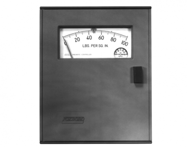
SCALE
Black markings on white background;
sector-shaped with nominal effective length of
150 mm (6 in).
CONNECTIONS
(Located in Bottom of Case)
PRESSURE AND VACUUM
• For upper range-values up to 14 MPa
(2000 psi, or 140 bar or kg/cm2):
Connections tapped for R1/4 or 1/4 NPT,
as specified.
• For upper range-values from 14 MPa
(2000 psi, or 140 bar or kg/cm2) up to
70 MPa (10.000 psi, or 700 bar or
kg/cm2): Connections threaded for R1/2
or 1/2 NPT, as specified.
• For upper range-values above 70 MPa
(10 000 psi, or 700 bar or kg/cm2):
9/16-18 Aminco® fitting used.
PNEUMATIC
• Supply and output connections tapped
for 1/4 NPT.
MOUNTING
PANEL
• Flush in a panel up to 16 mm (0.6 in) thick.
SURFACE
• Suitable for all controllers having
internally mounted elements.
PIPE
• A kit of parts to fit a DN 50 or 2 in vertical
pipe