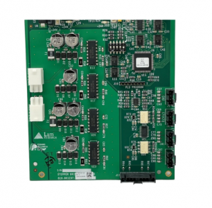
LAM 810-801237-021 Control and signal processing module
LAM Research 810-801237-021 is a typical VME Bus Controller/Interface Board.
Core control components in LAM Research’s 2300 series and Alliance series semiconductor etching/thin film deposition equipment.
Model 810-801237-xxx Introduction
The basic model 810-801237 belongs to the control and signal processing module.
Different suffixes (such as -021. -010. -022) represent different hardware versions or specific configuration differences:
Model type, main functions
810-801237-021 Current mainstream version of Interface/Logic Board.
It is responsible for handling the logical conversion of key signals and is often used for communication with external robots (KUKA) or vacuum valve controllers.
The 810-801237-010 Legacy Version, an early version, is mainly used on the older Alliance platform, with slightly weaker processing capabilities and anti-interference performance.
The 810-801237-022 Enhanced Version has optimized the firmware or capacitor specifications for the 300mm high-speed model.
3. Core Functions and Working Logic
810-801237-021
In the system containing the KUKA KRC2 controller, the role of 810-801237-021 is as follows:
VME node management: It is installed in the VME chassis of the host and serves as a communication node between the upper computer software and the underlying actuator (such as a robot).
Signal “relay station”
The host issues the “Take the chip” command.
810-801237-021 Confirm the safety signal (vacuum degree OK, valve open).
The signal is transmitted to the KUKA robot via DSE-IBS (00-117-336).
The robot moves and feeds its status back to the board card.
4. Common Fault Manifestations
If there is a problem with this board card, it usually leads to the following phenomena
VME Bus Scan Error: The host fails to recognize the board card in this slot when starting up.
Robot handshake timeout: The KUKA robot shows a waiting signal, but the host side shows that the signal has been sent.
Abnormal status light: If the LED indicator light on the front of the board shows a red (Fault) or remains dark, it usually indicates that the internal logic circuit is damaged or the power supply voltage (+5V/+12V) is unstable.
Maintenance suggestions
Considering the PH1003-2840 power supply you mentioned, the stability of this power supply directly affects the lifespan of such VME boards. If the 27V logic voltage fluctuates, it may cause the voltage divider circuit on 810-801237-021 to overheat and burn out.