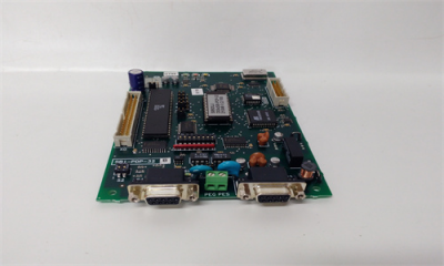
GE SBI-PDP-32 Control card
Profibus-DP is a field Bus designed for a fast data exchange relating to sensors
/ actuators; the communication is established between a Master central unit
(PLC or PC) and Slave units, i.e. sensors, actuators, drives, etc.
The data exchange is cyclic; the Master unit reads the Slaves input data and
writes the Slaves output data. The Bus cycle time is shorter than the cycle time
of the central unit; the Baud Rates for the Profibus-DP interface card are from
9.6 kbit/s to 12 Mbit/s according to Profibus-DP standard part. 3.
Il supporto fisico è quello standard Profibus-DP; al Bus possono essere colle
gati un numero massimo di 125 Slave.
The total cycle time depends on the number of Slaves connected; the 1.5
Mbit/s Baud Rate allows 8 drives to be polled in 6 milliseconds.
The physical support is standard Profibus-DP; the max. number of Slaves
connected to the Bus is 125
The Profibus-DP interface card is supplied with a kit including 4 spacers, 4
screws, washers and a 40-pole flat cable provided with connectors.
1. Switch the drive off.
2. Fasten the Profibus–DP interface card to the drive regulation board by
means of screws and spacerers. The Bus connectors have the same
direction of the regulation card terminals.
3. The Bus connectors have the same direction of the regulation card
terminals.
4. The BUS terminating resistances are connected or disconnected through
the S2 dip switch.
The last physical card in network shall have such resistances connected
in case the connector in use should not contain terminating resistances
itself.
SBI-PDP-32
ON = connected, OFF = disconnected.
5. The S1 dip switch determines the Slave address.
The addresses “0” and “1” are reserved to the Master and can not be used.
The switch S1-8 is not significant for the address and must always be set to
OFF. The address is only detected when the card is switched on. If the
address has been modified, the Profibus-DP interface card has first to be
switched off and then on in order assume the new address.
6. Connect the Bus cable to XS1 or XS2 connectors.
7. Switch on the drive.
8. The LEDs +5V and +5VE light up.
9. The LED DEA lights up when the communication enters in the Data
Exchange Phase.
2.3 Power supply
The Power supply is provided by the XO connector, which is also used to link
data between the Profibus-DP interface card and the drive regulation card.
Current draw 350mA.
2.4 Connectors
Connectors PEG:
Connectors XS
2.5 Dip Switches
It allows to connect set point of External Supply
Ground (GNDE) to the ground (PE).
It allows to connect the ground (PE) at the Profibus
cables shield
S3 Selection of interrupt source (INT1 / INT2) from S5 jumper to the 8032
microcontroller or the Dual Port Ram interrupt input (INTR). Default position
A (interrupt from the Dual Port Ram).
S4 Synchronization connection of the SBI-PDP card reset signal to the drive
regulation card reset signal. Default position ON.
S5 It is used to connect the INT_OPZ signal to the INT1 signal (S5 B) or to
the INT2 signal (S5 A). At the moment only the setting (default setting) of
the interface card as Option 1 is allowed, therefore INT_OPZ is connected
to the INT1 signal (default position A).
S6 It is used to connect the OUT_OPZ signal to the OUT1 (S6.A) or OUT2
(S6.B) signal. Default position A.
S7 It is used to connect the CEM_OPZ signal to the OPZ1 (S7.A) or OPZ2
(S7.B) signal. The default setting of the SBI-PDP card is Option 1. therefore
the CEM_OPZ signal is connected to the OPZ1 signal. Default position A.
S8 Connection of the Dual Port Ram BUSY signal to RDY_EXT signal. Default
position ON
S9 It is used for ibrid connection for communication. It allows to connect the
capacitor C3 (10nF 2kV) in case the connection is too long
S10It used for ibrid connection of the ground. It allows to connect the capacitor
C4 (10nF 2kV) in case the connection is too long.
2.6 LEDs
+5V +5V power supply.
RST Reset active.
DEA Data Exchange Phase active.
+5VE +5V power supply on the RS 485 driver side galvanic isolated.
2.7 Technical specification
Storage temperature:
Operating temperature:-20°… +70°C (-68…+158°F)
0°… +55°C (32…+131°F)
These temperatures are adequate to those of the drive, to which the cards are
connected.
2.8 Interface
The card shall be installed on the regulation card, so that the Profibus-DP
interface card X0 connector and the regulation card X0 connector are near to
each other always keeping connectors to the Profibus-DP line directed
downwards.
For the mechanical connection please use the kit supplied with the card.
For the electrical connection please use a 40-pin flat cable, also supplied.
For the connection to the Bus please use a shielded duplex cable.