FOXBORO Fieldbus Communications Module, FCM10Ef
I/ASeries® Hardware
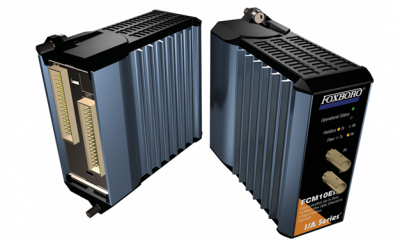
Fieldbus Communications Module, FCM10Ef
The FCM10Ef Fieldbus Communications Module is a
fiber optic communications interface which allows the
DIN rail mounted Fieldbus Modules (FBMs) to
communicate with the I/A Series control station over
extended distances using fiber optic cabling. The
FCM10Ef modules provide expanded networking,
easy customization, and greater overall cabling
distances in a fiber optic network (see Figure1). This
configuration is ideally suited for sites in which groups
of FBMs are to be spread apart over greater
distances.
FCM10Ef modules are used with multiport fiber optic
converters (hubs), which connect to the I/ASeries
control station via the high-speed, optionally
redundant 10 Mbps Ethernet trunk Fieldbus.
Up to six groupings of baseplate-mounted FCM10Ef
modules and FBMs can be linked to each optionally
redundant multiport fiber optic converter (hub), for a
maximum of 120 FBMs per I/A Series control station
(depending on selected scan periods). To support
redundancy, a pair of FCM10Ef modules must be
used for each FBM grouping. In non-redundant
configurations, only a single FCM10Ef is required for
each grouping.
Signal transmission distances up to 2 km (1.24 mi)
are possible between the FCM10Ef modules and the
multi-port fiber optic converters (hubs), providing for
wide distribution of the FBM equipment groupings.
Extended transmission distances, using fiber optic
cabling, are also possible within the groupings, and
between the multiport fiber optic converter (hub) and
the I/A Series control station. (Refer to
PSS21H-2W1B3. for details.)
FIBER OPTIC CABLING
FCM10Ef
Unaffected by electrical noise (EMI, RFI, and
lightning), fiber optic cabling provides a versatile,
highly reliable means of extending signal
communications. It can be used in areas containing
rotating machinery, arc welders, and so forth, and can
be installed in cable trays containing high voltage
power lines, or in outdoor areas exposed to lightning
hazards. Its electrical isolation characteristics provide
protection from voltage differentials and ground loops.
Fiber optic cabling used in this configuration is
purchased by the customer. The recommended fiber
optic cable is a multimode, graded-index glass fiber
with a 62.5 micron core and 125 micron cladding with
0.275 NA (numerical aperture).
Maximum allowable signal loss is 1 dB per km at a
wavelength of 1300 nm, and 3.6 dB per km at a
wavelength of 850 nm. Cables with different
characteristics may not be used. Four fiber optic
cables are required for redundancy, two for transmit
and two for receive connections. For this reason, it is
recommended that the customer purchase duplex
cabling, which consists of two fibers intertwined in a
single cable. The cables must be terminated with
ST-type connectors and cable length may not exceed
that specified for the module.
Other cable requirements (such as flexibility, or
durability) depend on the particular application. Check
with your cable vendor/installer for a listing of
application-specific cable characteristics.
FCM10Ef MODULE DESIGN
FCM10Ef modules convert 2 Mbps signals used by
the FBMs, to 10 Mbps fiber optic Ethernet signals
used with fiber optic cabling, and vice versa.
FCM10Ef modules have a compact design, with a
rugged extruded aluminum exterior for physical
protection of the circuits. Enclosures specially
designed for mounting of the FBMs and FCMs
provide various levels of environmental protection for
the FCM10Ef modules, up to harsh environments per
ISA Standard S71.04.
The FCM10Ef can be removed/replaced from the
baseplate without removing power.
Six light-emitting diodes (LEDs) incorporated into the
front of the FCM10Ef indicate the status of network
activity to/from the associated FBMs, and the
FCM10Ef module’s operational status.
FUNCTIONAL SPECIFICATIONS
Regulatory Compliance (Cont.)
INPUT VOLTAGE RANGE (REDUNDANT)
24 V dc +5%, -10%
CONSUMPTION
7 W (maximum) at 24 V dc
HEAT DISSIPATION
7 W (maximum) at 24 V dc
Vibration
0.75 g (5 to 200 Hz)
Calibration Requirements
Calibration of the module is not required.
Regulatory Compliance
ELECTROMAGNETIC COMPATIBILITY (EMC)
European EMC Directive 89/336/EEC
EN 50081-2 Emission standard
EN 50082-2 Immunity standard
IEC 61000-4-2 ESD Immunity
Contact 4 kV, air 8 kV
IEC 61000-4-3 Radiated Field Immunity
10 V/m at 80 to 1000 MHz
IEC 61000-4-4 Electrical Fast Transient/Burst
Immunity
2 kV
IEC 61000-4-5 Surge Immunity
2kV on ac and dc power lines; 1kV on I/O and
communications lines
IEC 61000-4-6 Immunity to Conducted
Disturbances
10 V
IEC 61000-4-8 Power Frequency Magnetic Field
Immunity
30 A/m
IEC 61000-4-11 Voltage Dips, Short Interruptions
and Voltage Variations Immunity
PRODUCT SAFETY
European Low Voltage Directive 73/23/EEC
PRODUCT CERTIFICATION
Underwriters Laboratories (UL)
UL/UL-C listed as suitable for use in UL/UL-C
listed Class I, Groups A-D; Division 2;
temperature code T4 enclosure based systems.
The modules are also UL and UL-C listed as
associated apparatus for supplying non
incendive communication circuits for Class I,
Groups A-D hazardous locations when
connected to specified I/A Series processor
modules as described in the I/A Series DIN Rail
Mounted FBM Subsystem User’s Guide
(B0400FA). Communications circuits also meet
the requirements for Class 2 as defined in Article
725 of the National Electrical Code (NFPA No.70)
and Section 16 of the Canadian Electrical Code
(CSA C22.1). Conditions of use are as specified
in the I/A Series DIN Rail Mounted FBM
Subsystem User’s Guide (B0400FA).
CENELEC
CENELEC (DEMKO) certified as EEx nA IIC T4
for use in CENELEC certified Zone 2 enclosure
based systems. The modules are CENELEC
certified as associated apparatus for supplying
non-incendive field circuits for Zone 2. Group IIC,
potentially explosive atmospheres when
connected to specified I/A Series processor
modules as described in the I/A Series DIN Rail
Mounted FBM Subsystem User’s Guide
(B0400FA).
EUROPEAN UNION COMPLIANCE
Meets all applicable European Union directives
including the Explosive Atmospheres (ATEX)
directive 94/9/EC, and bears the CE mark
FIBER OPTIC CABLING
Unaffected by electrical noise (EMI, RFI, and
lightning), fiber optic cabling provides a versatile,
highly reliable means of extending signal
communications. It can be used in areas containing
rotating machinery, arc welders, and so forth, and can
be installed in cable trays containing high voltage
power lines, or in outdoor areas exposed to lightning
hazards. Its electrical isolation characteristics provide
protection from voltage differentials and ground loops.
Fiber optic cabling used in this configuration is
purchased by the customer. The recommended fiber
optic cable is a multimode, graded-index glass fiber
with a 62.5 micron core and 125 micron cladding with
0.275 NA (numerical aperture).
Maximum allowable signal loss is 1 dB per km at a
wavelength of 1300 nm, and 3.6 dB per km at a
wavelength of 850 nm. Cables with different
characteristics may not be used. Four fiber optic
cables are required for redundancy, two for transmit
and two for receive connections. For this reason, it is
recommended that the customer purchase duplex
cabling, which consists of two fibers intertwined in a
single cable. The cables must be terminated with
ST-type connectors and cable length may not exceed
that specified for the module.
Other cable requirements (such as flexibility, or
durability) depend on the particular application. Check
with your cable vendor/installer for a listing of
application-specific cable characteristics.
FCM10Ef MODULE DESIGN
FCM10Ef modules convert 2 Mbps signals used by
the FBMs, to 10 Mbps fiber optic Ethernet signals
used with fiber optic cabling, and vice versa.
FCM10Ef modules have a compact design, with a
rugged extruded aluminum exterior for physical
protection of the circuits. Enclosures specially
designed for mounting of the FBMs and FCMs
provide various levels of environmental protection for
the FCM10Ef modules, up to harsh environments per
ISA Standard S71.04.
The FCM10Ef can be removed/replaced from the
baseplate without removing power.
Six light-emitting diodes (LEDs) incorporated into the
front of the FCM10Ef indicate the status of network
activity to/from the associated FBMs, and the
FCM10Ef module’s operational status.
FUNCTIONAL SPECIFICATIONS
Regulatory Compliance (Cont.)
INPUT VOLTAGE RANGE (REDUNDANT)
24 V dc +5%, -10%
CONSUMPTION
7 W (maximum) at 24 V dc
HEAT DISSIPATION
7 W (maximum) at 24 V dc
Vibration
0.75 g (5 to 200 Hz)
Calibration Requirements
Calibration of the module is not required.
Regulatory Compliance
ELECTROMAGNETIC COMPATIBILITY (EMC)
European EMC Directive 89/336/EEC
EN 50081-2 Emission standard
EN 50082-2 Immunity standard
IEC 61000-4-2 ESD Immunity
Contact 4 kV, air 8 kV
IEC 61000-4-3 Radiated Field Immunity
10 V/m at 80 to 1000 MHz
IEC 61000-4-4 Electrical Fast Transient/Burst
Immunity
2 kV
IEC 61000-4-5 Surge Immunity
2kV on ac and dc power lines; 1kV on I/O and
communications lines
IEC 61000-4-6 Immunity to Conducted
Disturbances
10 V
IEC 61000-4-8 Power Frequency Magnetic Field
Immunity
30 A/m
IEC 61000-4-11 Voltage Dips, Short Interruptions
and Voltage Variations Immunity
PRODUCT SAFETY
European Low Voltage Directive 73/23/EEC
PRODUCT CERTIFICATION
Underwriters Laboratories (UL)
UL/UL-C listed as suitable for use in UL/UL-C
listed Class I, Groups A-D; Division 2;
temperature code T4 enclosure based systems.
The modules are also UL and UL-C listed as
associated apparatus for supplying non
incendive communication circuits for Class I,
Groups A-D hazardous locations when
connected to specified I/A Series processor
modules as described in the I/A Series DIN Rail
Mounted FBM Subsystem User’s Guide
(B0400FA). Communications circuits also meet
the requirements for Class 2 as defined in Article
725 of the National Electrical Code (NFPA No.70)
and Section 16 of the Canadian Electrical Code
(CSA C22.1). Conditions of use are as specified
in the I/A Series DIN Rail Mounted FBM
Subsystem User’s Guide (B0400FA).
CENELEC
CENELEC (DEMKO) certified as EEx nA IIC T4
for use in CENELEC certified Zone 2 enclosure
based systems. The modules are CENELEC
certified as associated apparatus for supplying
non-incendive field circuits for Zone 2. Group IIC,
potentially explosive atmospheres when
connected to specified I/A Series processor
modules as described in the I/A Series DIN Rail
Mounted FBM Subsystem User’s Guide
(B0400FA).
EUROPEAN UNION COMPLIANCE
Meets all applicable European Union directives
including the Explosive Atmospheres (ATEX)
directive 94/9/EC, and bears the CE mark
Operating
TEMPERATURE-20 to +70°C (-4 to +158°F)
RELATIVE HUMIDITY
5 to 95% (noncondensing)
ALTITUDE
ENVIRONMENTAL SPECIFICATIONS(a)
Storage
TEMPERATURE-40 to +70°C (-40 to +158°F)
RELATIVE HUMIDITY
5 to 95% (noncondensing)
ALTITUDE-300 to +3.000 m (-1.000 to +10.000 ft)-300 to +12.000 m (-1.000 to +40.000 ft)
Contamination
Class G3 (Harsh) as defined in IS