FOXBORO Fieldbus Communications Module, FCM10E
FOXBORO Fieldbus Communications Module, FCM10E
I/ASeries® Hardware
Fieldbus Communications Module, FCM10E
The FCM10E Fieldbus Communications Module is a
communications interface which allows the DIN rail
mounted Fieldbus Modules (FBMs) to communicate
with I/A Series control stations via the high speed,
optionally redundant 10 Mbps Ethernet trunk Fieldbus
(see Figure1). The FCM10E converts 10 Mbps
Ethernet signals used by the control station to 2Mbps
signals used by the FBMs, and vice versa. They also
provide galvanic isolation between the 10 Mbps
Ethernet trunk Fieldbus and the 2Mbps module
Fieldbus.
The FCM10E modules are used in pairs for
redundancy. An FCM10E (or pair of FCM10E
modules) can support up to 30 FBMs.
FCM10E modules have a compact design, with a
rugged extruded aluminum exterior for physical
protection of the circuits. Up to 30 FCM10E pairs can
be connected to the Ethernet trunk Fieldbus.
Enclosures specially designed for mounting of DIN
rail mounted FBM equipment provide various levels of
environmental protection for the Fieldbus
Communications Modules, up to harsh environments
per ISA Standard S71.04.
The FCM10E can be removed/replaced without
removing power or communications cabling.
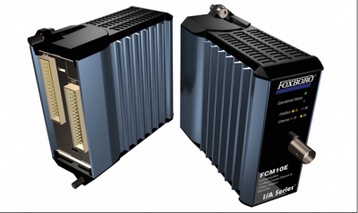
Six light-emitting diodes (LEDs), incorporated into the
front of the FCM10E Fieldbus Communications
Modules, indicate the status of network activity
to/from the control station and the associated FBMs,
and the operational status of the FCM10E.
For redundant configurations, two FCM10E modules
are required for each FBM grouping. A non-redundant
configuration requires a single FCM10E for each
grouping. Figure1 shows how FCM10E modules are
used in a typical subsystem configuration.
BASEPLATE MODULE MOUNTING
The FCM10E mounts on a baseplate, which is either
DIN rail mounted or rack mounted and includes signal
connectors for Fieldbus, power, and I/O cable
connections. A baseplate can support up to eight
FBMs, or a combination of FBMs and FCMs.
FUNCTIONAL SPECIFICATIONS
Regulatory Compliance (Cont.)
INPUT VOLTAGE RANGE (REDUNDANT)
24 V dc +5%, -10%
CONSUMPTION
7 W (maximum) at 24 V dc
HEAT DISSIPATION
7 W (maximum) at 24 V dc
Vibration
0.75 g (5 to 200 Hz)
Calibration Requirements
Calibration of the module is not required.
Regulatory Compliance
ELECTROMAGNETIC COMPATIBILITY (EMC)
European EMC Directive 89/336/EEC
EN 50081-2 Emission standard
EN 50082-2 Immunity standard
IEC 61000-4-2 ESD Immunity
Contact 4 kV, air 8 kV
IEC 61000-4-3 Radiated Field Immunity
10 V/m at 80 to 1000 MHz
IEC 61000-4-4 Electrical Fast Transient/Burst
Immunity
2 kV
IEC 61000-4-5 Surge Immunity
2kV on ac and dc power lines; 1kV on I/O and
communications lines
IEC 61000-4-6 Immunity to Conducted
Disturbances
10 V
IEC 61000-4-8 Power Frequency Magnetic Field
Immunity
30 A/m
IEC 61000-4-11 Voltage Dips, Short Interruptions
and Voltage Variations Immunity
Operating
PRODUCT SAFETY
European Low Voltage Directive 73/23/EEC
PRODUCT CERTIFICATION
Underwriters Laboratories (UL)
UL/UL-C listed as suitable for use in UL/UL-C
listed Class I, Groups A-D; Division 2;
temperature code T4 enclosure based systems.
The modules are also UL and UL-C listed as
associated apparatus for supplying non
incendive communication circuits for Class I,
Groups A-D, Division 2 hazardous locations
when connected to specified I/A Series
processor modules as described in the I/A Series
DIN Rail Mounted FBM Subsystem User’s Guide
(B0400FA). Communications circuits also meet
the requirements for Class 2 as defined in Article
725 of the National Electrical Code (NFPA No.70)
and Section 16 of the Canadian Electrical Code
(CSA C22.1). Conditions of use are as specified
in the I/A Series DIN Rail Mounted FBM
Subsystem User’s Guide (B0400FA).
FCM10E
CENELEC
CENELEC (DEMKO) certified as EEx nA IIC T4
for use in CENELEC certified Zone 2 enclosure
based systems. The modules are CENELEC
certified as associated apparatus for supplying
non-incendive field circuits for Zone 2. Group IIC,
potentially explosive atmospheres when
connected to specified I/A Series processor
modules as described in the I/A Series DIN Rail
Mounted FBM Subsystem User’s Guide
(B0400FA).
EUROPEAN UNION COMPLIANCE
Meets all applicable European Union directives
including the Explosive Atmospheres (ATEX)
directive 94/9/EC, and bears the CE mark.
ENVIRONMENTAL SPECIFICATIONS(a)
Storage
TEMPERATURE-20 to +70°C (-4 to +158°F)
RELATIVE HUMIDITY
5 to 95% (noncondensing)
ALTITUDE-300 to +3.000 m (-1.000 to +10.000 ft)
TEMPERATURE-40 to +70°C (-40 to +158°F)
RELATIVE HUMIDITY
5 to 95% (noncondensing)
ALTITUDE-300 to +12.000 m (-1.000 to +40.000 ft)
Contamination
Class G3 (Harsh) as defined in ISA Standard,
S71.04. Pollution degree 2 as defined in IEC 664-1.
PHYSICAL SPECIFICATIONS
Dimensions
FCM10E mounts on a baseplate. The baseplate can
be mounted on a DIN rail (horizontally or vertically),
or horizontally on a 19-inch rack using a mounting
kit. Refer to PSS 21H-2X2 B4 for details.
Mass
284 g (10 oz) approximate
33 Commercial Street
Foxboro, MA 02035-2099
United States of America
www.foxboro.com
HEIGHT
102 mm (4 in)
114 mm (4.5 in) including mounting lugs
WIDTH
45 mm (1.75 in)
DEPTH
104 mm (4.11 in)
Indicators (mounted on front of module)
Red and green light-emitting diodes (LEDs) provide
indication of the FCM operational status. Amber
LEDs indicate data traffic and direction