ABB ACS800-04 and ACS800-04M Drive Modules (45 to 560 kW)
ACS800-04/U4 product overview
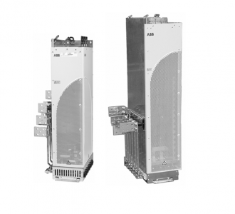
The ACS800-04/U4 is an IP00 drive module for controlling AC motors. It is to be
installed into a cabinet by the customer with base or wall fastening. The input cable
terminals are located at the top of the unit whereas the motor cable terminals are
located at the left- or right-hand side of the unit. The unit is delivered pre-assembled
with mounting pedestal and output busbars.
Slots for cables going to the RMIO board in the RDCU control unit. The cables are
coiled on the top of the module.
ACS800-04M product overview
The ACS800-04M is delivered as non-pre-assembled kits, which provide more
alternatives in assembling the units than the basic ACS800-04
Type designation label
The type designation label includes an IEC and NEMA rating, C-UL US, and CSA
markings, a type code and a serial number, which allow individual recognition of
each unit. The first digit of the serial number refers to the manufacturing plant. The
next four digits refer to the unit’s manufacturing year and week respectively. The
remaining digits complete the serial number so that there are no two units with the
same serial number.
The type designation label is located on the front cover and the serial number label
inside the unit. Example labels are shown below.
Type code
ACS800-04 and ACS800-04M
The type code contains information on the specifications and configuration of the
drive. The first digits from left express the basic configuration (for example,
ACS800-04-0170-5). The optional selections are given thereafter, separated by plus
signs (for example, +E202). The main selections are described below. Not all
selections are available for all types. For more information, refer to ACS800
Ordering Information (3AFY64556568, available on request).
Printed circuit boards
The drive contains the following printed circuit boards as standard:
• main circuit board (AINT)
• motor control and I/O board (RMIO) with a fibre optic link to the AINT board
• input bridge control board (AINP)
• input bridge protection board (AIBP) which includes snubbers for the thyristors
and varistors
• power supply board (APOW)
• gate driver control board (AGDR)
• diagnostics and panel interface board (ADPI)
• brake chopper control board (ABRC) with option +D150
Motor control
The motor control is based on the Direct Torque Control (DTC) method. Two phase
currents and DC link voltage are measured and used for the control. The third phase
current is measured for earth fault protection