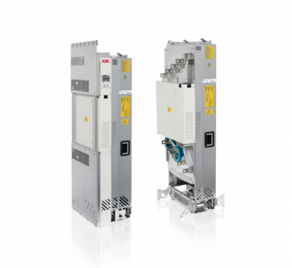
ABB ACS850-04 drive modules (160 to 560 kW, 200 to 700 hp)
What this chapter contains
This chapter guides in planning drive cabinets and installing the drive module into a
user-defined cabinet so that the front of the module faces the cabinet door. The
chapter gives cabinet layout examples and free space requirements around the
module for cooling. The issues discussed are essential for the safe and trouble-free
use of the drive system.
Limitation of liability
The installation must always be designed and made according to applicable local
laws and regulations. ABB does not assume any liability whatsoever for any
installation which breaches the local laws and/or other regulations.
Basic requirements for the cabinet
Use a cabinet which:
• has a frame sturdy enough to carry the weight of the drive components, control
circuitry and other equipment installed in it
• protects the user and drive module against contact and meets the requirements
for dust and humidity
• has sufficient air inlet and outlet gratings that allow free flow of cooling air through
the cabinet. This is critical for proper cooling of the drive module.
Planning the layout of the cabinet
Design a spacious layout to ensure easy installation and maintenance. Sufficient
cooling air flow, obligatory clearances, cables and cable support structures all
require space.
Place the control board(s) away from:
• main circuit components such as contactor, switches and power cables
• hot parts (heat sink, air outlet of the drive module).
Planning the electromagnetic compatibility (EMC) of the cabinet
Note following when planning the electromagnetic compatibility of the cabinet:
• Generally, the fewer and smaller the holes in the cabinet, the better the
interference attenuation. The maximum recommended diameter of a hole in
galvanic metal contact in the covering cabinet structure is 100 mm. Pay special
attention to the cooling air inlet and outlet gratings.
ACS850-04
• The best galvanic connection between the steel panels is achieved by welding
them together as no holes are necessary. If welding is not possible, the seams
between the panels are recommended to be left unpainted and equipped with
special conductive EMC strips to provide adequate galvanic connection. Usually,
reliable strips are made of flexible silicon mass covered with a metal mesh. The
non-tightened touch-contact of the metal surfaces is not sufficient, so a
conductive gasket between the surfaces is required. The maximum
recommended distance between assembly screws is 100 mm.
• Construct sufficient high-frequency grounding network in the cabinet to avoid
voltage differences and forming of high-impedance radiator structures. A good
high-frequency grounding is made with short flat copper braids for low
inductance. One-point high-frequency grounding cannot be used due to the long
distances inside the cabinet