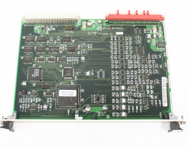
AMAT 0100-00398 | VME Interface System Control Board
AMAT 0100-00369 | VME 12-Channel High-Speed Stepper Motor Controller
Introduction
The AMAT 0100-00369 is an advanced 12-Channel Stepper Motor Controller Board manufactured by Applied Materials.
Designed for the high-performance VME (Versa Module Europa) bus architecture, this board is an essential motion control component for Centura, Endura,
and P5000 semiconductor platforms.
It provides the logic and pulse sequences required to manage up to 12 independent axes of motion, specializing in the precision movement of wafer handling robots, throttle valves, and lift assemblies within the processing chambers.
Technical Parameter Table
| Attribute | Specification |
| Manufacturer | Applied Materials (AMAT) |
| Model Number | 0100-00369 |
| Component Type | Printed Wiring Board (PWB) / Motion Controller |
| Bus Interface | VME Bus Standard |
| Control Capacity | 12 Independent Motor Channels |
| Compatibility | AMAT Centura 5200, Endura 5500, P5000 Phase IV |
| Output Signal | High-Speed Step/Direction (TTL/Differential) |
| Weight | 0.55 kg (approx. 1.21 lbs) |
| Power Requirements | +5V DC, +/-12V DC (via Backplane) |
| Form Factor | 6U VME Standard (160mm x 233mm) |
Unique Product Description
The AMAT 0100-00369 represents a high-density solution for sophisticated motion synchronization.
By consolidating 12 axes of control onto a single board, it allows for the seamless orchestration of complex wafer transfer maneuvers.
Unlike standard industrial controllers, the 0100-00369 features specialized acceleration/deceleration ramping algorithms that minimize mechanical vibration, which is critical for preventing particle generation during wafer transport.
Its design is hardened against electromagnetic interference (EMI), ensuring that precise motor positioning is maintained even in the presence of high-power RF fields used in plasma etching and deposition.
Product Advantages and Features
High-Density Motion Logic: Manages 12 axes simultaneously, optimizing slot usage within the system card cage.
Vibration Suppression: Smooth pulse-train generation reduces mechanical stress on wafer-contact components.
Real-Time Synchronization: Ensures all axes move in perfect harmony for complex R-Theta-Z robotic paths.
Optical Isolation: Protects the core VME bus logic from field-side electrical surges and noise.
Plug-and-Play Integration: Fully compatible with AMAT “Learn” and “Service” software modules for rapid calibration.
0100-00398
Related Models
AMAT 0100-00169: Standard 12-Channel Stepper Controller (earlier revision).
AMAT 0100-00137: Single-channel Stepper Interface Board.
AMAT 0010-20003: System Controller Card Cage Assembly.
AMAT 0190-01121: Multi-axis signal interconnect cable.
Other Models in the Same Series
The 0100-xxxxx series includes various specialized logic and communication PWBs:
0100-00370: High-speed digital I/O variant.
0100-01051: Single Board Computer (SBC) Master CPU.
0100-00007: VME Analog I/O Interface.
0100-00202: Advanced Motion Controller Board.
| ANDOVER | AC-1 |
| ANDOVER | CPU-8M |
| ANDOVER | PS120/240 |
| ANRITSU | Z-164A |
| ANSALDO | VME-SSI AVMESSI |
| ANSALDO | VP32502X 75X-6025-25 151-0025 |
| ANYBUS | ABDT-PDP 3183203131 |
| APPLIED MATERIALS | 0190-72680 |
| APTECH | DOT 4B 260/NSI541-210/M5900. FA-04-18 ATCS-15 |
| ARCHICE | 2150S |
| ARCHIVE | 2150ES |
| arcom | SHIM-8CE |
| AREVA | MVAJ27T1FB0784D |
| AREVA | MVAJ21T1GB0771B |
| AREVA | MVAJ23T1GB0774B |
| ASCO | H117AL112F1 |
Application Cases
Multi-Chamber Robots: Controlling the central transfer robot in Endura platforms to ensure precise wafer placement between chambers.
Chamber Lift Systems: Synchronizing the movement of the susceptor and pins to maintain wafer parallelism.
Vacuum Control: Managing the stepper motors for throttle valves to achieve fast and stable pressure setpoints.
Installation and Maintenance
Installation:
ESD Protection: Always use a grounded wrist strap. The 0100-00369 contains high-density logic chips sensitive to static.
Address Selection: Before insertion, ensure the onboard DIP switches or jumpers are correctly set to the designated system address.
Seating: Align with the card cage guide rails and use the injector handles to firmly lock the board into the backplane.
Maintenance:
Periodic Calibration: Run the system’s mechanical “Learn” procedures every 6 months to compensate for any minor hardware wear.
Contact Inspection: During annual PM, check the 96-pin DIN connectors for oxidation; clean with electronic-grade IPA if necessary.
System Logs: Monitor the system’s “Step Loss” or “Motion Error” logs to identify potential board or motor degradation before a failure occurs.