Phoenix QUINT-PS/96-110DC/24DC/10 – DC/DC converter 2905010
QUINT-PS/96-110DC/24DC/10 – DC/DC converter 2905010
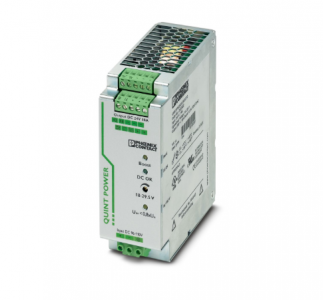
Primary-switched QUINT DC/DC converter with wide range input for DIN rail mounting with SFB (selective fuse breaking) technology, input:
96 – 110 V DC, output: 24 V DC/10 A
QUINT DC/DC converter with maximum functionality
DC/DC converters alter the voltage level, regenerate the voltage at the end of long cables or enable the creation of independent supply systems by means of electrical isolation.
QUINT DC/DC converters magnetically and therefore quickly trip circuit breakers with six times the nominal current, for selective and therefore cost-effective system protection.
The high level of system availability is additionally ensured, thanks to preventive function monitoring, as it reports critical operating states before errors occur.
Nominal input voltage range 96 V DC … 110 V DC
Input voltage range 67.2 V DC … 154 V DC
Wide-range input yes
Input voltage range DC 67.2 V DC … 154 V DC
Voltage type of supply voltage DC
Inrush current < 10 A (typical)
Inrush current integral (I2t) 0.37 A2s
Mains buffering time typ. 10 ms (96 V DC)
Current consumption 3.5 A (96 V DC)
3.1 A (110 V DC)
Reverse polarity protection , ≤ 154 V DC
Nominal power consumption 264 VA
Protective circuit Transient surge protection; Varistor
Input fuse 10 A 150 V DC (internal (device protection))
Efficiency > 92 % (UIN 96 V DC / UOUT 24 V DC)
> 92 % (UIN 110 V DC / UOUT 24 V DC)
Output characteristic U/I
Nominal output voltage 24 V DC ±1 %
Setting range of the output voltage (USet) 18 V DC … 29.5 V DC (> 24 V DC, constant capacity restricted)
Nominal output current (IN) 10 A (-40 °C … 60 °C)
POWER BOOST (IBoost) 12.5 A (-40 °C … 40 °C permanent, UOUT = 24 V DC)
Selective Fuse Breaking (ISFB) 60 A (12 ms)
Magnetic circuit breaker tripping B2 / B4 / B6
Derating 60 °C … 70 °C (2.5 %/K)
Feedback voltage resistance 35 V DC
Protection against overvoltage at the output (OVP) < 35 V DC
Max. capacitive load unlimited
Active current limitation 18 A
Control deviation < 1 % (change in load, static 10 % … 90 %)
< 2 % (change in load, dynamic 10 % … 90 %)
< 0.1 % (change in input voltage ±10 %)
Residual ripple < 20 mVPP
Output power 240 W
Peak switching voltages nominal load < 10 mVPP (20 MHz)
Maximum no-load power dissipation 4 W (UIN 110 V DC)
Power loss nominal load max. 22 W (UIN 110 V DC)
Rise time < 2 ms (UOUT (10 % … 90 %))
Connection in parallel yes, for redundancy and increased capacity
Connection in series yes
Fuse protection (secondary side) electronic
thermal-magnetic
thermal
2905010
Signal: DC OK active
Output description UOUT > 0.9 x UN: High signal
Switching voltage range 18 V DC … 24 V DC
Maximum inrush current < 20 mA (short-circuit-proof)
Signal: POWER BOOST, active
Output description IOUT < IN: High signal
Switching voltage range 18 V DC … 24 V DC
Maximum inrush current < 20 mA (short-circuit-proof)
Signal: UIN OK, active
Output description UIN > 19.2 V: High signal
Switching voltage range 18 V DC … 24 V DC
Maximum inrush current ≤ 20 mA (short-circuit-proof)
Signal: DC OK floating
Output description Relay
Input
Connection method Screw connection
Conductor cross-section, rigid min. 0.2 mm²
Conductor cross-section, rigid max. 2.5 mm²
Conductor cross-section flexible min. 0.2 mm²
Conductor cross-section flexible max. 2.5 mm²
Conductor cross-section AWG min. 24
Conductor cross-section AWG max. 12
Stripping length 8 mm
Screw thread M3
Tightening torque, min 0.5 Nm
Tightening torque max 0.6 Nm
Output
Connection method Screw connection
Conductor cross-section, rigid min. 0.2 mm²
Conductor cross-section, rigid max. 2.5 mm²
Conductor cross-section flexible min. 0.2 mm²
Conductor cross-section flexible max. 2.5 mm²
Conductor cross-section AWG min. 24
Conductor cross-section AWG max. 12
Stripping length 7 mm
Screw thread M3
Tightening torque, min 0.5 Nm
Tightening torque max 0.6 Nm
Signal
Conductor cross-section, rigid min. 0.2 mm²
Conductor cross-section, rigid max. 2.5 mm²
Conductor cross-section flexible min. 0.2 mm²
Conductor cross-section flexible max. 2.5 mm²
Conductor cross-section AWG min. 24
Conductor cross-section AWG max. 12
Screw thread M3
Tightening torque, min 0.5 Nm
Tightening torque max 0.6 Nm
Types of signaling LED
Active switching output
Relay contact
Signal output: DC OK active
Status display “DC OK” LED green
Color green
Signal output: POWER BOOST, active
Status display “BOOST” LED yellow/IOUT > IN : LED on
Color yellow
Note on status display LED on
Signal output: UIN OK, active
Status display LED “UIN < 0.8 x UN V” yellow/UIN < 0.8 x UN V DC: LED on
Color yellow
Note on status display LED on
Number of phases 1
Insulation voltage input/output 1.5 kV (type test)
1 kV (routine test)
1 kV (type test)
Product family QUINT POWER
MTBF (IEC 61709. SN 29500) > 1357000 h (25 °C)
> 772000 h (40 °C)
Insulation characteristics
Protection class I
Degree of pollution 2
Width 48 mm
Height 130 mm
Depth 125 mm
Installation dimensions
Installation distance right/left 0 mm / 0 mm (≤ 70 °C)
Installation distance right/left (active) 15 mm / 15 mm (≤ 70 °C)
Installation distance top/bottom 50 mm / 50 mm (≤ 70 °C)
Installation distance top/bottom (active) 50 mm / 50 mm (≤ 70 °C)
Alternative assembly
Width 122 mm
Height 130 mm
Depth 51 mm
| METSO | A413659 |
| METSO | A413310 |
| METSO | A413313 |
| METSO | D100532 |
| METSO | A413222 |
| METSO | A413177 |
| METSO | A413345 |
| METSO | S420154 |
| METSO | S420071 |
| METSO | S420061 |
| METSO | S422737 |
| METSO | IOP303 |
| METSO | R/I-TB 9139041 |