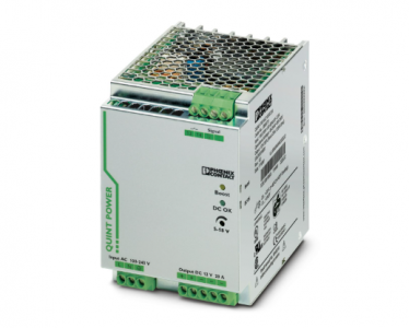
Phoenix QUINT-PS/1AC/12DC/20 – Power supply 2866721
QUINT-PS/1AC/12DC/20 – Power supply
2866721
2866721
Primary-switched power supply unit QUINT POWER, Screw connection, SFB Technology (Selective Fuse Breaking),
input: 1-phase, output: 12 V DC / 20 A, adjustable from 5 V DC … 18 V DC, 90 V DC … 350 V DC
Nominal input voltage range 100 V AC … 240 V AC
Input voltage range 85 V AC … 264 V AC
90 V DC … 350 V DC (UL 508: ≤ 250 V DC)
Input voltage range AC 85 V AC … 264 V AC
Input voltage range DC 90 V DC … 350 V DC (UL 508: ≤ 250 V DC)
Electric strength, max. 300 V AC
Voltage type of supply voltage AC
Inrush current < 20 A (typical)
Inrush current integral (I2t) < 3.2 A2s
AC frequency range 45 Hz … 65 Hz
Frequency range DC 0 Hz
Mains buffering time typ. 40 ms (120 V AC)
typ. 40 ms (230 V AC)
Current consumption 2.4 A (120 V AC)
1.4 A (230 V AC)
2.5 A (110 V DC)
1.2 A (220 V DC)
Nominal power consumption 311 VA
Protective circuit Transient surge protection; Varistor
Typical response time < 1 s
Input fuse 12 A (slow-blow, internal)
Permissible backup fuse B10 B16 AC:
Permissible DC backup fuse DC: Connect a suitable fuse upstream
Recommended breaker for input protection 10 A … 16 A (AC: Characteristics B, C, D, K)
Discharge current to PE < 3.5 mA
DC operation
Voltage type of supply voltage DC
Efficiency > 90 % (for 230 V AC and nominal values)
Output characteristic U/I
Nominal output voltage 12 V DC ±1 %
Setting range of the output voltage (USet) 5 V DC … 18 V DC (> 12 V DC, constant capacity restricted)
Nominal output current (IN) 20 A (-25 °C … 60 °C)
POWER BOOST (IBoost) 26 A (-25 °C … 40 °C permanent)
Selective Fuse Breaking (ISFB) 120 A (12 ms)
Magnetic circuit breaker tripping B2 / B4 / B6 / B10 / C2 / C4 / C6
Derating 60 °C … 70 °C (2.5 %/K)
Feedback voltage resistance max. 25 V DC
Protection against overvoltage at the output (OVP) < 25 V DC
Control deviation < 1 % (change in load, static 10 % … 90 %)
< 2 % (change in load, dynamic 10 % … 90 %)
< 0.1 % (change in input voltage ±10 %)
Residual ripple < 50 mVPP (with nominal values)
Output power 240 W
Maximum no-load power dissipation 6 W
Power loss nominal load max. 29 W
Rise time < 0.5 ms (UOUT (10 % … 90 %))
Connection in parallel yes, for redundancy and increased capacity
Connection in series yes
Fuse protection (secondary side) electronic
thermal-magnetic
thermal
Signal: DC OK active
Output description UOUT > 0.9 x UN: High signal
Switching voltage range 5 V DC … 12 V DC
Output voltage 12 V DC
Maximum inrush current ≤ 20 mA (short-circuit-proof)
Continuous load current ≤ 20 mA
Signal: DC OK floating
Output description Relay contact, UOUT > 0.9 x UN: Contact closed
Maximum switching voltage 30 V AC
24 V DC
Maximum inrush current 0.5 A
1 A
Continuous load current 1 A
Signal: POWER BOOST, active
Output description IOUT < IN: High signal
Switching voltage range 5 V DC … 12 V DC
Output voltage 12 V DC
Maximum inrush current ≤ 20 mA (short-circuit-proof)
Continuous load current ≤ 20 mA
Connection method Screw connection
Conductor cross-section, rigid min. 0.2 mm²
Conductor cross-section, rigid max. 6 mm²
Conductor cross-section flexible min. 0.2 mm²
Conductor cross-section flexible max. 4 mm²
Conductor cross-section AWG min. 18
Conductor cross-section AWG max. 10
Stripping length 7 mm
Screw thread M3
Tightening torque, min 0.5 Nm
Tightening torque max 0.6 Nm
Output
Connection method Screw connection
Conductor cross-section, rigid min. 0.2 mm²
Conductor cross-section, rigid max. 6 mm²
Conductor cross-section flexible min. 0.2 mm²
Conductor cross-section flexible max. 4 mm²
Conductor cross-section AWG min. 12
Conductor cross-section AWG max. 10
Stripping length 7 mm
Screw thread M3
Tightening torque, min 0.5 Nm
Tightening torque max 0.6 Nm
Signal
Connection method Screw connection
Conductor cross-section, rigid min. 0.2 mm²
Conductor cross-section, rigid max. 6 mm²
Conductor cross-section flexible min. 0.2 mm²
Conductor cross-section flexible max. 4 mm²
Conductor cross-section AWG min. 18
Conductor cross-section AWG max. 10
Screw thread M3
Tightening torque, min 0.5 Nm
Tightening torque max 0.6 Nm
Types of signaling LED
Active switching output
Relay contact
Signal output: DC OK active
Status display UOUT > 0.9 x UN: “DC OK” LED green
Note on status display UOUT < 0.9 x UN: Flashing “DC OK” LED
IOUT < IN: LED ON
Signal output: DC OK floating
Status display UOUT > 0.9 x UN: “DC OK” LED green
Note on status display UOUT < 0.9 x UN: Flashing “DC OK” LED
Signal output: POWER BOOST, active
Status display IOUT > IN: LED “BOOST” yellow