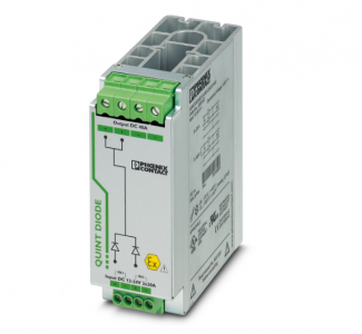
Phoenix 2320157 QUINT-DIODE/12-24DC/2X20/1X40 – Redundancy module
QUINT-DIODE/12-24DC/2X20/1X40 – Redundancy module
2320157
IN rail diode module 12-24 V DC/2×20 A or 1×40 A. Uniform redundancy up to the consumer.
A safe redundant system is the result of the parallel connection of two power supply units which are decoupled from one another.
To further increase system availability, QUINT DIODE provides the solution: decoupling with diode.
DC operation
Nominal input voltage range 12 V DC … 24 V DC
Input voltage range 10 V DC … 30 V DC
Voltage type of supply voltage DC
Reverse polarity protection yes, < 60 V
Nominal input current (IN) 2x 20 A (-25 °C … 60 °C)
1x 40 A (-25 °C … 60 °C)
Maximum current Imax 2x 30 A (-25 °C … 40 °C)
1x 60 A (-25 °C … 40 °C)
Transient surge protection Varistor
Voltage drop, input/output typ. 0.5 V
Nominal input voltage range 12 V DC … 24 V DC
Input voltage range 10 V DC … 30 V DC
Input voltage range DC 10 V DC … 30 V DC
Efficiency > 97 %
Nominal output voltage UIn – 0.5 V
Nominal output current (IN) 40 A (Increasing power)
20 A (Redundancy)
Derating 60 °C … 70 °C (2.5 %/K)
Power loss nominal load max. 10 W (IOUT = 20 A)
Connection in series no
Derating 60 °C … 70 °C 2.5 %/K
Connection method Screw connection
Conductor cross-section, rigid min. 0.2 mm²
Conductor cross-section, rigid max. 6 mm²
Conductor cross-section flexible min. 0.2 mm²
Conductor cross-section flexible max. 4 mm²
Conductor cross-section AWG min. 12
Conductor cross-section AWG max. 10
Stripping length 8 mm
Screw thread M3
Tightening torque, min 0.5 Nm
Tightening torque max 0.6 Nm
Output
QUINT-DIODE/12-24DC/2X20/1X40
Connection method Screw connection
Conductor cross-section, rigid min. 0.5 mm²
Conductor cross-section, rigid max. 16 mm²
Conductor cross-section flexible min. 0.5 mm²
Conductor cross-section flexible max. 16 mm²
Conductor cross-section AWG min. 10
Conductor cross-section AWG max. 6
Stripping length 10 mm
Screw thread M4
Tightening torque, min 1.2 Nm
Tightening torque max 1.5 Nm
Product family QUINT DIODE
MTBF (IEC 61709. SN 29500) 40000000 h
LED no
Insulation characteristics
Protection class III
Degree of pollution 2
Width 50 mm
Height 130 mm
Depth 125 mm
Horizontal pitch 2.8 Div.
Installation dimensions
Installation distance right/left 5 mm / 5 mm
Installation distance top/bottom 50 mm / 50 mm
Mounting type DIN rail mounting
Assembly note alignable: PN ≥50%, 5 mm horizontally, 15 mm next to active components, 50 mm vertically
alignable: PN <50%, 0 mm horizontally, 40 mm vertically top, 20 mm vertically bottom
Mounting position horizontal DIN rail NS 35. EN 60715
Flammability rating according to UL 94 (housing / terminal blocks) V0
Housing material Metal
Housing material Steel sheet, zinc-plated
Degree of protection IP20
Ambient temperature (operation) -40 °C … 70 °C (> 60 °C Derating: 2.5 %/K)
Ambient temperature (storage/transport) -40 °C … 85 °C
Maximum altitude ≤ 5000 m
Climatic class 3K3 (in acc. with EN 60721)
Max. permissible relative humidity (operation) ≤ 95 % (at 25 °C, non-condensing)
Shock 18 ms, 30g, in each space direction (according to IEC 60068-2-27)
Vibration (operation) < 15 Hz, amplitude ±2.5 mm (according to IEC 60068-2-6)
15 Hz … 150 Hz, 2.3g, 90 min.
Temp code T4 (-25 … +70 °C; > 60 °C, Derating: 2.5 %/K)
Standard – Electronic equipment for use in electrical power installations and their assembly into electrical power installations EN 50178/VDE 0160 (PELV)
Standard – Electrical safety EN 60950-1/VDE 0805 (SELV)
Standard – Protection against shock currents, basic requirements for protective separation in electrical equipment EN 50178
Standard – Safety extra-low voltage IEC 60950-1 (SELV) and EN 60204-1 (PELV)
Standard – Safe isolation DIN VDE 0100-410
UL approvals UL/C-UL listed UL 508
UL/C-UL Recognized UL 60950-1
UL ANSI/ISA-12.12.01 Class I, Division 2. Groups A, B, C, D T3C … T4 (Hazardous Location)
Conformity/Approvals
ATEX II 3 G Ex ec IIC T4 Gc
DEKRA 20ATEX0041 X
IECEx Ex ec IIC T4 Gc
IECEx DEK 20.0022X
Electromagnetic compatibility Conformance with EMC Directive 2014/30/EU
Low Voltage Directive Conformance with Low Voltage Directive 2014/35/EC
EMC requirements for noise emission EN 61000-6-3
EN 61000-6-4
EMC requirements for noise immunity EN 61000-6-1
EN 61000-6-2
Surge voltage load (surge)
Standards/regulations EN 61000-4-5
Surge voltage load (surge)
Input 2 kV (level 3 – asymmetrical: conductor to ground)
1 kV (Level 2 – symmetrical: Conductor to conductor)
Output 2 kV (level 3 – asymmetrical: conductor to ground)
1 kV (Level 2 – symmetrical: Conductor to conductor)
Comments Criterion A
Surge current load (surge)
Standards/regulations EN 61000-4-5
Surge current load (surge)
Input 2 kV (level 3 – asymmetrical: conductor to ground)
1 kV (Level 2 – symmetrical: Conductor to conductor)
Output 2 kV (level 3 – asymmetrical: conductor to ground)
1 kV (Level 2 – symmetrical: Conductor to conductor)
Emitted interference
Standards/regulations EN 61000-6-3
Radio interference voltage in acc. with EN 55011 EN 55011 (EN 55022) Class B, area of application: Industry and residential
Emitted radio interference in acc. with EN 55011 EN 55011 (EN 55022) Class B, area of application: Industry and residential