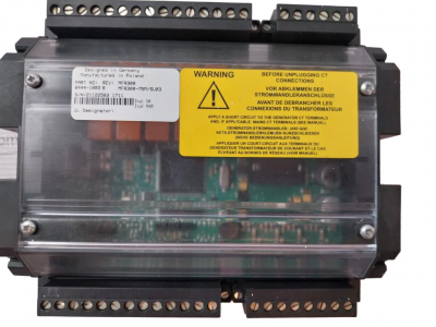
Woodward MFR300 75M/SU03, Transducer 8444-1093 8444-1094 8444-1095
Woodward MFR300 75M/SU03, Transducer 8444-1093 8444-1094 8444-1095
Product number: 8444-1093
Manufacturer product number: 8444-1093
Description: woodward: MFR300 75M/SU03. Transducer
Unbalanced Load (Level 1 & 2) ANSI# 46
General notes
Unbalanced load is monitored according to how the parameters “Voltage measuring”
(parameter ╚═▷ 1851), “Current measuring” (parameter ╚═▷ 1850) and “Phase rotation”
(parameter ╚═▷ 3954) are configured
A vector/phase shift is defined as the sudden variation of the
voltage curve which may be caused by a major source load
change.
8444-1093
The unit measures the duration of a cycle, where a new measure
ment is started with each voltage passing through zero. The meas
ured cycle duration will be compared with an internal quartz-cali
brated reference time to determine the cycle duration difference of
the voltage signal.
A vector/phase shift as shown in Fig. 37 causes a premature or
delayed zero passage. The determined cycle duration difference
corresponds with the occurring phase shift angle.
The monitoring may be carried out three-phase or one/three
phase. The monitoring can be configured in different ways. The
vector/phase shift monitor can also be used as an additional
method to decouple from the grid. Vector/phase shift monitoring is
only enabled after the monitored voltage exceeds 50% of the PT
secondary rated voltage
The unbalanced load alarm is a phase imbalance alarm. Unbalanced load is determined
by calculating the negative sequence component of a three phase system: The three
current components and the angle between them. Parameter “Monitoring Modes”
(parameter ╚═▷ 2414) defines how to calculate in detail accoring to typical standards.
Unbalanced load monitoring is only active if “Current measuring” (parameter ╚═▷ 1850) is
configured to “L1 L2 L3” and “Voltage measuring” (parameter ╚═▷ 1851) is either
configured to “3Ph 4W” or “3Ph 3W”. The threshold is defined as the percentage of that
value relative to the nominal current. The protective function is triggered if this
percentage value is exceeded.
Voltage Asymmetry (Level 1 & 2)
General notes
Voltage asymmetry is determined by calculating the negative sequence component of a
three-phase system. This value is derived from the three delta voltages (phase-phase).
Voltage asymmetry monitoring is only active if “Voltage measuring” (parameter ╚═▷
1851) is configured to “3Ph 4W” or “3Ph 3W”. The threshold is defined as the percentage
of that value relative to the nominal delta voltage. The protective function is triggered if
this percentage value is exceeded.
| HIMA | F8652E 984865264 |
| HIMA | F3236 984323602 |
| HIMA | Z7130 |
| HIMA | H6200A |
| HIMA | SB3073-EX |
| HIMA | KFD2-VR4-Ex1.26 |
| HIMA | KFD2-STC4-Ex1 |
| HIMA | TM591-B00-G00 |
| HIMA | TM521-A02-B00-C02-D00-E01-G00-I0-M1 |
| HIMA | TM202-A00-B00-C00-D00-E00-G00 |
| HIMA | K7214 996721402 |
| HIMA | K1412B 996141261 H51q-HRS B5233-2 997205233 |
| HIMA | B9302 997009302 |
| HIMA | F8650 |
| HIMA | F-PWR02 |
| HIMA | F2DO1601 |
| HIMA | F8650E |