Woodward High Output DVP, 10KW TB Input/Output 8200-536
High Output DVP, 10KW TB Input/Output 8200-536
High Output DVP, 10KW
TB Input/Output
8200-536
TB Input/Output, SIL Certified
8200-545
TB Input/Output, Servo Interface Module (SIM)
8200-586
The DVP device may be controlled via CAN communication. There are three possible CAN modes:
1. CANopen single with or without analog backup
2. CANopen dual
3. CANopen virtual
1. The CANopen single with or without backup:
This mode uses CAN port 1 for communication. Optionally, it is possible to configure (by CAN
communication) the analog input as a backup signal. By default, the analog input is a backup signal.
(See analog input section for how to interface and setup an analog input.)
2. CANopen Dual:
This mode uses CAN port 1 and CAN port 2. If the two ports are working correctly, information
received from CAN port 1 is used. If communication by CAN port 1 is not possible any more (detected
by communication time out), CAN port 2 is used for communication.
3. CANopen Virtual:
This mode is used when two DVPs are linked together to control more than one actuator or valve. This
is used for Dual Redundant DVP Operation.
The CAN communication baud rate can be selected. The possible options are:
• 125 kbps
• 250 kbps
• 500 kbps
Per CiA DS-102 Standard, the following are the recommended maximum cable lengths. Differences in the
baud rate and the cable length affect the number of units that can be put onto a network.
If CAN port 1 is used, see Figure 3-13 of the CAN port interface. See the Analog Input section above for
the analog interface diagram when CAN is used with an Analog Input backup.
Pins 29 and 30 are the termination jumper. Connecting these two pins with a short wire on the connector
will enable an internal 120 Ω resistor between CAN high and CAN low wire.
Pins 31 and Pin 32 are the CAN High and CAN low wires typically found on a CAN system.
Pins 33 and 34 are two additional CAN high and CAN low pins. These can be used to daisy chain the
CANbus to the next device, without the need for a junction box.
Pin 35 is the CAN ground. The DVP side of the CAN link is galvanically isolated from the DVP, ground,
and system common. Therefore, we need to connect the isolated ground to the ground of the user
control.
Pin 36 is used to terminate the CAN wiring shield.
When using dual can communication mode, there are two identical communication ports. Port 1 and Port 2 are
wired identically. For description, see Port 1.
Table 3-16. Dual CAN Communication Wiring Specifications
DVP1000-S
Pin Number Function
29 CAN 1 Termination jumper
30 CAN 1 Termination jumper
31 CAN 1 High in
32 CAN 1 Low in
33 CAN 1 High out
34 CAN 1 Low out
35 CAN 1 ISO GND
36 CAN 1 Shield
37 CAN 2 Termination jumper
38 CAN 2 Termination jumper
39 CAN 2 High in
40 CAN 2 Low in
41 CAN 2 High out
42 CAN 2 Low out
43 CAN 2 ISO GND
44 CAN 2 Shield
See Appendix A for more information on CANopen communications.
3.14.1 CAN Node ID Selection
When using CANopen communications, it is necessary to set the CAN Node ID to a unique value to
ensure that the DVP responds to commands intended for the appropriate device. There are two methods
for setting this value— software or hardware/wiring. The method is defaulted to a predetermined
configuration based on the DVP part number but can be changed using the Service Tool (see manual
26912). With the software option, the node ID setting is a user-defined value set in software. The
hardware/wiring (also referred to as harness coding) option uses discrete inputs to select an index which
sets the node ID value. The index is determined by the power-up state of the discrete inputs. Note that
the discrete input condition is based on open or closed state at power-up, ignoring the active high/low
configuration. Changes to any Node ID-related software settings require a power cycle to take effect.
The discrete input CAN ID selection has three different options. The index can be based on two, three, or
four discrete inputs, allowing three, seven, or 15 valid preprogrammed settings. This selection method is
set using the Service Tool as part of the CAN demand configuration. Tables 3-17. 3-18. and 3-19 identify
the selected index based on the configured selection method.
Definitions:
• Discrete Input 5: connection between terminal 24 and GROUND
• Discrete Input 4: connection between terminal 23 and GROUND
• Discrete Input 3: connection between terminal 22 and GROUND
• Discrete Input 2: connection between terminal 21 and GROUND
• Discrete Input 1: connection between terminal 20 and GROUND
• (GROUND can be any terminal 25. 26 or 27)
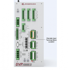
3.14.2 Instructions for Use of CAN ID Terminal Blocks
When using the harness coding method (as described in Section 3.14.1), it is necessary to install a
jumper terminal block within each positioner during initial installation. This terminal block configures each
positioner for proper communication with its assigned primary or secondary CAN Open Network. The
installation of this terminal block must be performed before attempting power-up or communications
across the CAN Open Network. Until this process is complete, the positioners will not communicate with
the networks. Install jumpers based on the CAN ID Node Selection and using the information from the
appropriate table (3-17. 3-18. and/or 3-19).
Proper installation of the CAN ID Terminal Blocks is performed by the following steps:
1. Ensure that there is no power being applied to the DVPs.
2. Determine which DVP will be connected to the Primary CAN Network, and which will be connected to
the Secondary CAN Network.
3. Create the appropriate CAN ID Terminal Block associated with each CAN Network.