Vertex Compressor Control 8200-1370
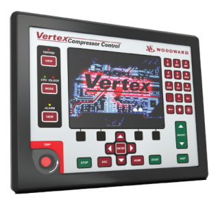
able 1-1 lists models with an integrated display. Models with display are panel mounted and include acolor graphical display that has the capability of customization to unique compressor, OEM, and customerrequirements.
Part Number8200-13708200-13718200-1372Figure 1-1.
Vertex Compressor Control (With Display)WoodwardReleasedChapter 1.
General InformationIntroductionPart Number OptionsTable 1-1.
Vertex (with display) Part Number OptionsPowerLVDC (18-36 Vdc) Ordinary Location ComplianceAC/DC (88-264 Vac or 90-150 Vdc) Ordinary Locations ComplianceATEX Compliance LVDC (18-36 Vdc
Table 1-2 lists models without an integrated display.
These models are a bulkhead-mounted version ofthe Vertex. Configured without a display, the Vertex without a display is ideal for remote environments.Table 1-2.
Vertex (without display) Part Number OptionsPart Number8200-13808200-13818200-1382Figure 1-2.
Vertex Compressor Control (Without Display)General Installation and Operating Notes and WarningsThe Standard Low Voltage and High Voltage Controls are suitable for use in ordinary locations only.
TheLow Voltage ATEX Control is suitable for use in Class I, Division 2. Groups A, B, C, and D or Class I,European Zone 2. Group IIC environments or non-hazardous locations.
These listings are limited only to those units bearing the certification identification.Field wiring must be stranded copper wire rated at least 75 °C for operating ambient temperaturesexpected to exceed 50 °C.Peripheral equipment must be suitable for the location in which it is used.
Wiring must be in accordance with North American Class I, Division 2. or European Zone 2 wiringmethods as applicable, and in accordance with the authority having jurisdiction.
WoodwardReleasedPowerLVDC (18-36 Vdc) Ordinary Location ComplianceAC/DC (88-264 Vac or 90-150 Vdc) Ordinary Locations ComplianceATEX Compliance LVDC (18-36 Vdc
General DescriptionThe Vertex Compressor Control is field programmable which allows a single design to be used in manydifferent control applications and reduces both cost and delivery time.
Vertex
It uses a built in graphical userinterface (GUI) with multi-lingual menu driven screens to instruct site engineers on configuring the controlto a specific compressor application. The Vertex can be configured to operate as a stand-alone unit or inconjunction with a plant’s Distributed Control System.
The Vertex control has 12 PID controllers that can affect the controlled operation of the compressor.
1. Anti-Surge PID Stage 1
2. Suction Pressure Override Stage 1
3. Discharge Pressure Override Stage 1
4. Rate Control PID Stage 1
5. Anti-Surge PID Stage 2
6. Suction Pressure Override Stage 2
7. Discharge Pressure Override Stage 2
8. Rate Control PID Stage 2
9. Performance Control PID
10. Performance Limiter 1 PID
11. Performance Limiter 2 PID
12. Load Sharing PID
Depending on the configuration of the Vertex, these PIDs may be used or not used. Please refer to theBlock diagrams listed later in this chapter to fully understand PID relationships.
Anti-Surge Control
The Vertex can be applied to protect one or two section compressor trains from surge.
The control isconfigured with the OEM provided compressor performance map which describes the Surge Limit Line.
ASurge Control Line with a configured margin away from the Surge Limit Line is generated.
The controllercontinuously monitors the current operating point of the compressor and compares it with the SurgeControl Line to determine if opening of the Anti-surge valve is necessary.
The Vertex control protectsagainst surge by modulating one or two Anti-Surge Valves (or blow-off valve) while keeping processconditions within acceptable limits.
Performance Control
The Vertex has a Performance Controller (PFC) which is commonly configured to drive suction/dischargethrottle valves, Inlet Guide Vane position, or speed control setpoint.
When configured, this control functionis used to control compressor suction pressure, compressor discharge pressure, compressor flow, or anyprocess variable related to compressor flow or load.
This control function compares an analog inputsignal to an internal setpoint and, depending on the programmed configuration, positions the compressorthrottle valve, inlet guide vanes, torque converter, and/or motor speed (VFD) to accomplish the desiredcontrol.
Figure 1-1 shows an example of a compressor application with a typical 1-section, 1-valve compressortrain.
Figure 1-2 shows an example of a compressor application with a typical 2-section, 2-valvecompressor train
Vertex (18-36 VDC, Standard Compliance) Compressor Control 8200-1370
Vertex (88–264 VAC or 90-150 VDC, Standard Compliance) Compressor
Control
8200-1371
Vertex (18-36 VDC, ATEX Compliance) Compressor Control 8200-1372
VertexDR (18-36 VDC, Standard Compliance) Compressor Control 8200-1373
VertexDR (88-264 VAC or 90-150 VDC, Standard Compliance) Compressor
Control
8200-1374
VertexDR (18-36 VDC, ATEX Compliance) Compressor Control 8200-1375
Flex500DR FTM Kit – DR FTM, Interconnection Cables
*Documentation: Spec: 03437. Manuals: 35072V1. 35072V2. 35072V3
5541-705
Auxiliaries
Distributed I/O Module – RTCnet RTD (100/200ohm) 8200-1100
Distributed I/O Module – RTCnet T/C (Fail High) 8200-1101
Distributed I/O Module – RTCnet AIO Loop power 8200-1103
Distributed I/O Module – RTCnet DIN (16ch) 8200-1104
Distributed I/O Module – RTCnet DOUT (16ch) 8200-1105
RemoteView Software License 8928-5311
*Documentation: FTM Configuration Instructions; Manual 26838 (page 65.
Appendix)