Woodward 85018V2 505E Digital Governor for Extraction Steam Turbines
85018V2
505E Digital Governor
for Extraction Steam Turbines
505 HMI Software
Woodward offers two different HMI software packages, OpView and 505View,
which allow an operator to remotely view operating inputs, adjust control
setpoints, issue Run mode commands, and monitor/troubleshoot the turbine
control. Both HMI packages are self-configuring which eliminates all field
engineering—they automatically configure their screens to match the control’s
programmed application.
The OpView is comprised of an industrialized NEMA 4 touchscreen hardware
package bundles together with a Woodward developed software interface
program. The 505View is a unbundled Intellution-based software package that
runs on a pc (hardware can be optionally purchased). Both HMI packages are
pre-configured to communicate via Modbus® * protocol with either a 505 or 505E
Woodward steam turbine control and offer the following features.
*—Modbus is a trademark of Schneider Automation Inc.
Automatic Screen Generation based on control configuration
Security with multiple User Levels
Remote Access Capability1
Real-Time and Historical Trending2
Alarm/Trip Status Indication
Alarm/Trip Log with Time Tagging and First-Out Indication
I/O and System Troubleshooting
Graphic System Control screens
Event Status Logging and History3
Notes:
1 505View only
2 OpView has Real-Time Trending only; 505View has both
3 OpView has Logging only; 505View has Logging and History
automatically configures its screens to match the 505E’s programmed
application. If the 505E is not configured to accept Modbus commands, the HMI
functions as a system monitor only. If the 505E is configured to accept Modbus
commands, all 505E Run Mode operations can be monitored and performed
through it (start, stop, mode enable/disable, setpoint raise/lower). For safety
purposes, the Overspeed test function can not be performed through the HMI.
See Volume 1. Chapter 7 of this manual for more information on programming
Modbus ports.
User-friendly touch screens allow operators to view and control multiple modes of
operation and setpoints from one screen. Ten different screens are available to
allow operators the flexibility of viewing. These screens display the following
85018V1
information:
Controlling parameter information
Complete starting sequences
Turbine and/or Generator information
Speed, Extr/Adm, Aux, Casc, & Limiter information
Analog Input and Output levels
Contact Input and Relay Output states
Alarm and Shutdown Log
The OpView or 505View can interface with the 505E through serial RS232.
RS422. or RS485 communications. By using RS422 or RS485 communications,
the HMI can be located up to 4.000ft (1.220meters) from the 505E digital control.
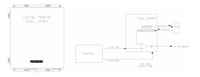
Digital Remote Final Driver
Digital Remote Final Driver (DRFD) is used to interface the 505E digital control to
existing valve operators or Woodward actuators that are integrating in action or
are not compatible with the 505E.
The 505E’s actuator outputs have the capability of driving a 4–20 mA or 20–160
mA (200 mA max) proportional signal into an actuator coil. These 505E actuator
output signals represent a demand signal equal to desired valve position
(proportional). If the application’s actuator or servo assembly requires a different
drive signal, or control action (integrating with a null setting), a Digital Remote
Final Driver or equivalent device must be used.
Woodward Digital Remote Final Drivers accept a 4–20 mA actuator-drive signal
proportional to desired valve position, and position a servo assembly accordingly.
Integrating or proportional type DRFDs are available depending on the servo
assembly being interfaced to. Woodward DRFDs have the capability of driving
unipolar or bipolar actuator demand signals, up to 0–400 mA or +400 mA
respectively.
The Digital Remote Final Driver is housed in a NEMA-4X enclosure with a hinged
cover and consists of driver and power supply modules. The driver module uses
plug-in jumpers and an alphanumeric display to facilitate field configuration and
calibration.
Proportional type DRFDs can provide an output drive signal of up to 400 mA, to
be compatible with existing servo assemblies. This drive signal is proportional to
the 4–20 mA input signal received from the 505E digital control.
Integrating type DRFDs sense actual valve position (through, LVDTs, RVDTs,
MLDTs, or DC position feedback devices), compare this signal to the input
position demand signal from the 505E, and output a drive signal to position a
servo assembly accordingly. See Figure 1-2.
Please refer to Woodward Product Spec 85532 for more information on DRFDs
and their capabilities.
Real Power Sensor
A Real Power Sensor is used to sense the real power produced by a generator
or flowing through a tie line. Woodward Real Power Sensors sense three-phase
volts, three-phase amps, compare each phase’s voltage to current relationship,
and develop a 4–20 mA output proportional to real power.
Woodward manufactures two types of Real Power Sensors. The first type of RPS
is designed to sense power flow in one direction only (0 to +5 A CT current only),
and output a proportional 4–20 mA signal. This type of RPS was designed for
and should be used to sense generator power output. Many different real power
sensors of this type exist. Some of the optional RPS features include VAR
sensing, Loadsharing, 0–1 A CT current sensing, and multiple combinations of
these. Please consult a Woodward certified distributor or a Woodward factory for
the recommended RPS for your application.
The second type of RPS manufactured by Woodward is designed to sense
power flow through a bus-to-bus tie line. This RPS (8272-726) senses –5A to
+5A CT current to allow its output to represent power flow in both directions. This
RPS provides a 4–20 mA power indication output signal where 12 mA represents
0 power flow. It is recommended that this RPS be used to sense power flow
through a tie line only. This RPS or equivalent is required to sense plant Import
and Export power.
Woodward Real Power Sensors have terminals labeled “Output” and terminals
labeled “KW Readout”. The “KW Readout” terminals provide a 4–20 mA signal
proportional to real power which is used by and compatible with the 505E control.
Thus the RPS terminals labeled “Output” are designed and typically compatible
only to Woodward’s 2301 type of control
Woodward manufactured Real Power Sensors have a 2.5 Hz Low pass filter (400
ms lag time) on their output to filter out the high frequency noise typically created
in a switch gear type environment. Thus if another vendor’s watt transducer is
used, verification that it has similar filtering criteria should be performed before it
is applied with the 505E. For more information on Woodward Real Power
Sensors, please refer to Woodward manual 82018.
Digital Synchronizer and Load Control (DSLC™)
The Woodward DSLC™ is a microprocessor based generator load control
designed for use on three-phase AC generators with Woodward speed controls
and automatic voltage regulators. The DSLC is a synchronizer, a load control, a
dead bus closing system, a VAR/PF control, and a process control, integrated
into one package.
The 505E can be programmed to use the DSLC as a synchronizer only, or as a
synchronizer and load control. The DSLC provides either phase match or slip
frequency synchronizing, and ties into the unit automatic voltage regulator to
match voltages before paralleling. It interfaces with the 505E via a Speed bias
signal to control generator frequency and phase. When configured to use the
DSLC as a synchronizer only, the 505E must be programmed to receive the
DSLC Speed Bias signal through an analog input and have this input enabled
through a contact input or function key.
The DSLC communicates over a LAN using a digital Echelon network with other
system DSLCs to enable it to perform safe deadbus closings. Because the DSLC
performs all synchronizing functions simultaneously, synchronization typically
takes only a few seconds.
When used as a synchronizer and load control, the DSLC performs automatic
synchronization, and controls unit load based on the DSLCs mode of operation.
The DSLC can be in a base-load, loadsharing, remote load setting, or Process
control mode, depending on configuration and system conditions.
The DSLC’s baseload mode of operation allows an operator to set the unit to a
specified load. A proportional or integrating control action can be used with this
mode of operation. The integrating mode of operation can be used with systems
tying to an unstable grid to allow the unit to control at a constant load and not
vary based on grid frequency.
The DSLC’s loadsharing mode is used to share load with any other units using a
DSLC and tied to the same isolated bus. This mode is used in conjunction with a
Master Synchronizer & Load Control when paralleled to a utility to allow the
MSLC to control plant frequency or load depending on its state of operation.
The DSLC’s remote load setting mode allows load to be set by a remote 4–20
mA signal. The DSLC’s Process control mode allows any process directly related
to generator load to be controlled.
When using the DSLC as both a synchronizer and load control, the 505E control
must be programmed to receive the DSLC Speed Bias signal through an analog
input and have this input enabled through a contact input or function key.
After synchronization, unit load can be controlled by the DSLC (through the 505E
Sync/Ld input) or by the 505E’s internal speed/load setpoint. When the Sync/Ld
Share input is programmed, the position of the Utility Tie Breaker Contact selects
unit load control through the DSLC or through the 505E’s internal load setpoint.
The DSLC interfaces to the 505E via a Speed Bias signal. From the many
different types of DSLCs manufactured by Woodward only a few have a Speed
Bias output (1–5 Vdc) compatible with the 505E control. The 505E’s isolated
analog #6 input is the only analog input that is directly compatible with the DSLC.
Thus the DSLC’s speed bias output should only be connected to the # 6 analog
input. The DSLC’s speed bias output is designed to drive into the 505E’s low
impedance input.
Once the generator is synchronized the DSLC soft-loads the unit to the load
setting determined by the mode of operation (base load, loadsharing, Process
control). When commanded the DSLC can also soft-unload the unit and issue a
breaker-open command at a set power level.
Installation Notes
Hand-held Programmer (9905-292) is required and used by the DSLC to
configure and calibrate it to the site specific application.
The DSLC requires a power source of +24Vdc @ 1 A. The 505E power supplies
can not supply this much power, thus an external power supply may be required.
The DSLC can interface with the unit Automatic Voltage Regulator through
contacts or a +9 volt bias signal.
For more information on Woodward’s Digital Synchronizer & Load Control,
please refer to Woodward manual 02007.