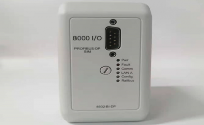
8502-BI-DP Bus interface modules
8502-BI-DP Bus interface modules
Profibus protocol
◆ links MTL8000 node to Profibus-DP host LAN
◆ supports up to 24 I/O modules
◆ HART process & status variables over Profibus-DP
◆ extended diagnostics for module and channel status
◆ LAN speeds of up to 6 Mbaud
◆ non-volatile memory for configuration
◆ software configurable via local port or Profibus host
◆ HART® maintenance via Comms adaptor
The 8502-BI-DP Bus Interface Module (BIM) provides the
communications link between the 8000 series I/O modules and a
Profibus-DP host. Its high speed acquisition of data from the modules
and LAN operation speeds of up to 6 Mbaud allows the host to
respond rapidly to conditions in the control process.
The BIM gathers the data from the I/O modules and makes it
available to the host upon request. It is a slave to the Profibus master.
As well as cyclic data exchange, which is required for reading input
and writing output data, the BIM supports Profibus Extended
Diagnostics for status information. It also supports a number of
special features which have been implemented to allow high
integrity system operation and in-situ maintenance.
PARAMETERISATION
The 8502 supports parameterisation from the Profibus master. This
configures on a “per module” basis, i.e. all the channels on a single
module carry the same configuration. The configuration is created in
a Profibus configurator using details provided in a GSD file.
This method is fast and enables a configuration to be built based
upon “logical” modules which represent the physical modules.
Modules are added one at a time to the configuration and
parameters are chosen to apply to all the channels of the module.
Logical modules can be selected to provide HART status and process
variables in the Profibus-DP cyclic input telegram. In addition, for
applications where access to many HART variables is required, the
HART “mailbox” can be used. This technique collects HART variable
as they are required; saving space in telegrams that are sometimes
overworked with data. This method is available only when using
parameterisation.
8502-BI-DP
The configuration is passed down from the Profibus master to the BIM
at the start of the session. If the system is stopped and re-started, the
configuration file is re-transmitted to the BIM.
CONFIGURATION
The alternative to parameterisation is the use of the 8455-SW-CF
configuration software. This enables the user to configure individual
channels and alarms and store the configuration in the BIM. The
configuration can also be saved to the 8510-MO-NS Node Services
Module for instant recovery if a BIM has to be replaced.
Configuration by this method uses a different GSD file to the one
used for parameterisation and the data frame is based on “data
blocks” rather than on a “by module” approach. The 8455 software
automatically provides a map of the data created in the telegram to
enable host programmers to identify the data passed.
HART status and process variables can be communicated to the
Profibus-DP host in the cyclic input telegram.
I/O & HART data requires space in the DP data frame as shown in
the table below.
The Profibus BIM supports both Standard and Extended Diagnostics.
While the Standard Diagnostics provide standard PROFIBUS status
information, the Extended Diagnostics provide detailed information
relating to the status of the BIM, the health of the modules and the
status of I/O channels. Depending on the I/O module type, events
such as high and low alarm, open circuit and line fault are detected.
Extended Diagnostic messages are generated on detection of an
anomaly and also when it is cleared. Use of the diagnostic capability
requires suitable support in the host application.
For hosts unable to use diagnostic data in the control algorithm, it is
possible to map the diagnostic data into the input dataframe.
HART DEVICE MAINTENANCE
Pass through messaging to HART devices is available via the local
configuration port and the 8512 HART Comms interface. This allows
multi-dropping of a number of BIMs on an RS485 link to a PC
running a wide range of instrument management software.