FOXBORO FBM208/b, Redundant with Readback, 0 to 20 mA I/O Module
FOXBORO FBM208/b, Redundant with Readback, 0 to 20 mA I/O Module
Overview
Single input/single output control schemes with high availability requirements can take
advantage of the FBM208 arranged as a redundant pair. A readback feature is
provided that detects failures of the output channel. In a repair situation, when a single
module is replaced, the inputs and outputs are maintained by the redundant module.
HART
signals are electrically compatible with the 4-20 mA signals, permitting the
plant to upgrade field devices without the need to change the control system. The
FBM208b provides the same functionality and is used to upgrade from the older
FBM05.
Aredundant pair of the modules combine to provide redundancy at the Fieldbus
Module (FBM) level, with field I/O wired to one common termination assembly (TA)
(see Figure 1. page 4). Each module independently attempts to hold the output(s) at
its specified output value(s), and each independently reports its observed value of the
inputs.
Aredundant analog input and redundant analog output block in the Foxboro
DCS
Control Software validates each input and output in conjunction with information to/
from the module.
FBM208
The FBM208is electrically compatible with standard HARTsignals.
• Four0to20mADCanaloginputchannels
• Four0to20mADCanalogoutputchannels with readback
• ComparesFBM’soutput value with the current readback value. If the readback
value differs from the desired output by more than ± 2%, the FBM marks its
output channel BAD.
• Monitors FBM’s internal channel current loop power and marks the channel BAD
if power is less than 16 VDC
• Marking achannel Bad causes the corresponding channel in the redundant
module to continue to drive the outputs
• Redundantmodules increase reliability
• Termination Assemblies (TAs) for locally or remotely connecting field wiring to the
FBM208
The FBMcomparesits output value with the current readback value. If the readback
value differs from the desired output by more than ±2%, the FBM marks its output
channel BAD. In addition, if the output value is greater than the desired output by
more than +2%, the power to that channel is shut off to help prevent the bad channel
from interfering with the control of that channel by the redundant partner FBM. The
power to a detected failed channel remains off until the FBM is replaced or rebooted
by the user.
Whenthe FBM’soutput channel is marked BAD, the CP presents that information to
the Foxboro DCS for display as a System Management alarm message and as a
control block alarm.
Redundant Analog Inputs
Each input channel accepts an analog sensor input such as a 4 to 20 mA transmitter
or a self-powered 4 to 20 mA source.
Transmitter power from each module is diode OR’d together in the redundant adapter
to help assure redundant power.
Aredundant analog input function block, AINR, is used for each redundant pair of
inputs. The AINR block handles input reads and initialization logic for the redundant
channels. On each execution cycle of the AINR block, identical reads are sent to both
modules, fully exercising the fieldbus and the logic circuitry of each module.
Input channel options include a configurable choice of integration time on a per
module basis. Input channel availability is enhanced by redundantly powering the
input current loop from per channel power supplies in each module of the pair.
Redundant Analog Outputs
Each output channel drives an external load and produces a 0 to 20 mA output.
Aredundant analog output block, AOUTR, is used for each redundant pair of outputs.
The AOUTRblock handles output writes and initialization logic for the redundant
channels. On each execution cycle of the AOUTR block, identical output writes are
sent to both modules, fully exercising the fieldbus and the logic circuitry of each
module. When a failure is detected in one of the modules, its output is driven to 0 mA
and the corresponding channel in the good module automatically continues supplying
the proper current to the output current loop.
Configurable options in the modules for output failsafe and fallback options are always
set to their default values (0 mA). This removes one of the pair of redundant output
channels from service for detectable problems such as a module not properly
receiving output writes or not passing diagnostic tests on FBM microprocessor writes
to output registers. Using the default failsafe/fallback options of 0 mA output also
minimizes the possibility of a “fail high” result.
High Accuracy
High Reliability
For high accuracy, the module incorporates sigma-delta converters for each channel.
This provides new analog input readings every 25 ms and a configurable integration
period to remove any process noise and power line frequencies. Each time period, the
FBMconverts each analog input to a digital value, averages these values over the
time period and provides the averaged value to the controller.
The redundancy of the module pair, coupled with the high coverage of detected faults,
provides a very high subsystem availability time.
The microprocessor of each module executes the analog I/O application program,
plus diagnostic routines that validate the health of the FBM.
Either module may be replaced without upsetting field input or output signals to the
good module. The module can be removed/replaced without removing field device
termination cabling, power, or communications cabling.
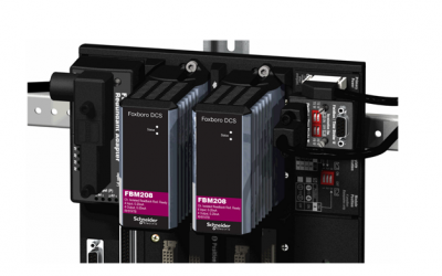
Light-emitting diodes (LEDs) incorporated into the front of the module provide visual
indications of the module’s operational status.
Standard Design
FBM208/208b has a rugged extruded aluminum exterior for physical protection of the
circuits. Enclosures specially designed for mounting the FBMs provide various levels
of environmental protection, up to harsh environments.