FOXBORO E69F-BI2 Signal converter
FOXBORO E69F-BI2 Signal converter
E69F Current-to-Pneumatic
Signal Converter
Introduction
General Description
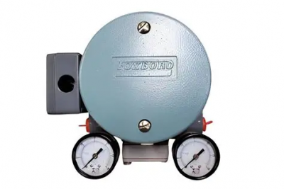
TheE69F Current-to-Pneumatic Signal Converter (Figure 1) is a field-mounted instrument that
transforms a dc milliampere input signal to a proportional pneumatic output signal.
This output signal can be used either to operate such pneumatic devices as dampers, and valve
actuators, and so forth, or as the input to various pneumatic instruments.
Principle of Operation
A dc milliampere input signal is converted to a proportional pneumatic output signal in the fol
lowing manner (see Figure 2). A coil positioned in the field of a permanent magnet reacts to the
current by producing a tangential thrust proportional to the input signal flowing through it. The
thrust, acting through coil flexures, varies the gap between a flapper and a nozzle. This causes a
change in the output pressure of the relay, which is also the converter output pressure. This pres
sure is fed to a feedback bellows which exerts a force on a feedback flexure to move the nozzle and
establish a throttling relationship between the flapper and the nozzle
Standard Specifications
Input and Output Ranges
Input Ranges (mA)
1.3 m3/h (0.75 cfm) at standard conditions with 140 kPa or 20 psi supply.
1.7 m3/h (1.0 cfm) at standard conditions with 240 kPa or 35 psi supply.
Ambient Temperature Limits
Normal Operating Conditions:-30 and +60°C (-20 and +140°F)
Operative Limits: -40 and +80°C (-40 and +180°F)
Calibrated Accuracy
±0.5% of span; but ±2% of span with output signals of 7 to 125 and 7 to 220 kPa or 1 to 18
and 1 to 32 psi
Mass
(Approximate) 2.3 kg (5 lb)
Product Safety
For electrical classification of converter, refer to data plate. For conditions of certification, refer to
Calibration
For simplicity, the procedure below assumes a converter with a 4 to 20 mA input and a 20 to
100 kPa or 3 to 15 psi output. For other ranges, substitute the applicable values. The specific
input and output are listed on the converter data plate.
Equipment Setup
Calibration setup is shown in Figure 7.
Any adjustment to the span will interact with the zero adjustment and will change
the initial zero setting. Therefore, any adjustment made to the span must be
followed by readjustment of zero.
1. Set up equipment as shown in Figure 7.
2. Apply 12 mA (50%) input to converter and adjust output (zero screw) to 60 kPa or
9 psi (50%). See Figure 8.
E69F-BI2
3. Apply 20 mA (100%) input to converter and note amount of error above or below
100 kPa or 15 psi (100%) output. If error is greater than ±2% (1.6 kPa or 0.025 psi),
perform Step 4. If error is less than ±2%, proceed to Step 5.
4. Loosen 5/16-inch bellows locknut. Note reference line on bellows. Rotate bellows1 so
that reference line moves toward motor to decrease span or away from motor to
increase span until the error is within ±2%. Tighten bellows locknut.
Repeat Steps 2 and 3.
5. See Figure 9. Loosen the 5/16-inch span locknut and turn the 5/16-inch span
adjustment nut a proportional amount (noted in Step 3) based on the following: 1/6
of a turn (point to point on the hexagonal nut) corrects the error by 0.5%.
7. Apply 12 mA (50%) input to converter and adjust output (zero screw) to 60 kPa or
9 psi (50%).