ABB Digital output module ICSO 08 R1, 8 relay outputs 2 A
Intended purpose
The digital output module ICSO 08 R1 is used as a re
mote module on the CS31 system bus. It contains 8 relay
output channels with the following features:
The relay outputs
are electrically isolated (from each other and
from the rest of the module and
can be loaded with 2 A.
The module is available for supply voltages of 24 V DC
and 230 V AC. For electrical connection, it has to be
mounted on a plug-in base ECZ.
The CS31 system bus interface is electrically isolated from
the rest of the module.
The module offers a number of diagnosis functions (see
chapter “Diagnosis and displays”).
Display and operating elements on the
front panel
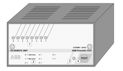
ICSO 08 R1,
8 yellow LEDs to indicate the signal status of the
outputs or for displaying error and diagnosis data
List of diagnosis information concerning the
LEDs when they are used for diagnosis display
Red LED for error message
Test button
Electrical connection
The module has to be mounted on the plug-in base ECZ
and then fastened with two screws. The plug-in base has
a mechanical coding which prevents that a module can
be plugged-in with another supply voltage than set on the
ECZ. Before mounting the input module, the mechanical
coding has to be set to the correct supply voltage.
The following three figures show the electrical connection
of the output module.
Addressing
An address must be set for each module to enable the
basic unit to correctly access the outputs.
The address setting is accomplished with the DIL switch
on the plug-in base ECZ. When using the basic units
07 KR 91 and 07 KT 9x as bus masters, the following
address assignments are valid:
A detailed description about “Addressing” can be
found in the chapter “Addressing” of the basic units
and couplers.
The module uses 8 outputs on the CS31 system bus.
I/O configuration
An I/O configuration is not necessary.
Normal operation
After power ON the module initializes automatically.
During this period the red LED (3) flashes.
After initialization the red LED (3) goes out, if the bus
runs correctly and if the module has detected no error.
The 8 yellow LEDs (1) indicate the signal statuses of
the channels A0…A7.
Diagnosis and displays
Diagnosis functions:– Error inside the module– Error on the CS31 system bus
If one of these errors occurs, the red LED (3) lights up.
Using the test button (4) and the LEDs (1), diagnosis in
formation can be achieved directly at the module.