ABB Basic Units 07 KT 97, 07 KT 96, 07 KT 95 Advant Controller 31
Advant Controller 31
Intelligent Decentralized
Automation System
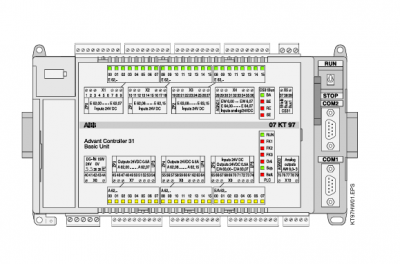
Basic Unit 07 KT 97
Basic unit with max. 480 kB user program
+ 256 kB user data, CS31 system bus
Fig. 2.1-1: Basic unit 07 KT 97 R0200
The basic unit 07 KT 97 R200 is the standard device for all applications. In addition, there are basic units with reduced
performance (e.g. 07 KT 95 or 07 KT 96) as well as ones with extended performance (e.g. 07 KT 97 R260 with
ARCNET connection, 07 KT 97 R0220 with PROFIBUS connection and 07 KT 97 R0262 with both ARCNET and
PROFIBUS connection). A comparison table is given on page 3. This document describes the basic unit 07 KT 97
R200 and then adds the data sheets of the other devices which only show the differences.
2.1.1 Brief description
The basic unit 07 KT 97 works either as
bus master in the decentralized automation system
Advant Controller 31 or as
slave (remote processor) in the decentralized automa
tion system Advant Controller 31 or as
stand-alone basic unit.
The basic unit is powered by 24 V DC.
2.1.1.1 Main features
24 digital inputs with LED displays
16 digital transistor outputs with LED displays
8 digital inputs/outputs with LED displays
8 individually configurable analog inputs 0…10 V,
0…5 V, ±10 V, ±5 V, 0…20 mA, 4…20 mA, differential
inputs, Pt100 (2-wire or 3-wire), the analog inputs are
also individually configurable as digital inputs
4 individually configurable analog outputs ±10 V,
0…20 mA, 4…20 mA
2 counters for counting frequencies up to 50 kHz, con
figurable in 7 different operating modes
1 CS31 system bus interface for system expansion
1 interface for connecting communication modules
(e.g. 07 KP 90)
2 serial interfaces COM1. COM2– as MODBUS interfaces and– for programming and test functions
Real-time clock
LEDs for displaying operating conditions and error
messages
Detachable screw-type terminal blocks
Fastening by screws or by snapping the device onto a
DIN rail
The lithium battery 07 LE 90 can be put into the
battery compartment in order to– store and backup the user program in the RAM– store and backup data which is additionally con
tained in the RAM, e.g. the status of flags– backup the time and date (real-time clock)
RUN/STOP switch for starting and aborting the pro
gram execution
Extensive diagnosis functions– self-diagnosis of the basic unit– diagnosis of the CS31 system bus and the
connected modules