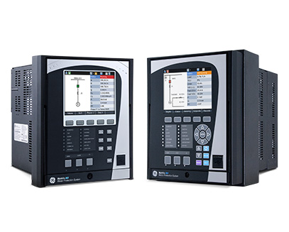
GE Multilin 859 Comprehensive and Compact Motor Protection
The Multilin 859 Motor Protection System, a member of the Multilin 8 Series protective relay platform, is designed for the protection, control and management of medium and large power rating induction motors. It has also been purpose built as a direct replacement for GE’s existing range of Multilin motor protection relays including the 169, 269, 269Plus, and 369 devices.
Based on the same field proven hardware and protection and control algorithms of the Multilin 8 Series, the 859 delivers advanced features including high-speed protection, customizable programmable logic, and advanced motor monitoring and diagnostics – all in a fixed mount, slim design.
With extensive communication capabilities the 859 easily integrates into new or existing process control systems, enabling operationally focused motor management and control
To simplify the migration and upgrade from existing Multilin 169, 269/269Plus, and 369 protection relays, the 859 has the same cutout and depth. In the case of replacing a 369 relay, the 859 has the same terminal arrangement, eliminating the need to change field wiring. In the case of other relays, detailed one-to-one wire maps and setting file conversion tools are provided to significantly simplify the upgrade process.
Multilin 859 Overview
The Multilin 859 Motor Protection System is a protection device for managing, protecting and controlling medium to large horsepower motors.
With a fast protection pass, running every 1/8th of a cycle, the 859 relay provides fast current, voltage, power and frequency protection elements; reducing stress on the motor. The Multilin 859 supports the latest standard communications protocols, including IEC 62439/PRP and IEC 61850 Ed. 2 ; facilitating easy integration into new and existing SCADA/DCS networks.
Key Benefits
- Utilizing GE’s proven Thermal Model for reliable protection of AC induction motors
- With a depth of 3.5″, the 859 is ideal for MCCs with shallow depths or space constraints
- Detachable display can be mounted up to 15 feet away from the device, allowing for greater installation flexibility
- Large graphical color LCD display enhanced operability, with user-configurable single line diagrams for local control, system status and metering
- Integrated condition monitoring based on Electrical Signature Analysis, delivering detailed monitoring & analytics for extended motor life
- CyberSentry™ Advanced Security including features such as AAA, Radius, RBAC, and Syslog. helping to enable NERC® CIP compliance
- Safe and reliable motor re-start on ‘down hole’ pump applications. Unique back spin detection feature detects flow reversal on a pump motor, enabling timely and safe motor restarting
- Single setup & configuration software, reducing training & commissioning time
- Customer Support available 24/7, available in multiple languages
-
High-Inertia Load Applications
The voltage-dependent overload curve feature in the Thermal Model protects motors that are used in high-inertia-load applications. Voltage is continually monitored when the motor is started and during acceleration. The thermal-limit curve is then adjusted accordingly. This enables the Multilin 859 to distinguish between a locked-rotor condition, an accelerating condition, and a running condition.
VFD-Driven Motor Applications
The Multilin 859 provides protection for motors fed through VFDs (Variable Frequency Drives). A wide range of the frequency tracking (3-72 Hz) allows the 859 to track the motor frequency and adjust its sampling rate to accurately measure phasors. An advanced algorithm allows switchable current and voltage tracking in case VFD is bypassed.
Thermal protection also considers the extra heating generated by the greater harmonics due to the VFD, to achieve an accurate response to the actual motor heating. RMS currents fed to the various motor-protection elements are further processed through the averaging filter to eliminate oscillations in current signals to ensure security.
Additionally, users can indicate a starting VFD frequency that helps the device track the motor frequency faster. Therefore, the 859 accurately measures the phasor quantities, which, otherwise, could cause delayed or false protection operation.
Cyclic Load Motor Applications
Input currents of a motor driving cyclic load can vary between very small to greater than the maximum allowable current during a load cycle. Variation in current magnitude results in motor heating and cooling depending on the heat and cooling time constants. Thermal overload protection response is adaptive to the cyclic load based on the cooling time constants. In addition, to provide more accurate overload thermal model response to cyclic load, the input currents to the thermal model are averaged over the settable duty-cycle interval. With a reciprocating-load application, the number of cycles to average can be determined from current waveform capture using the Oscillography/Datalogger features in the GE motor-protection relays