ABB Numerical Generator Protection REG216
ABB Numerical Generator Protection REG216
REG612
Features • Modular hardware • Selectable protection functions • Multitude of applications • Menu-assisted setting with PC • Fully numerical signal processing • Continuous self-monitoring of hardware • Cyclical testing routines mostly performed by the software • Setting of parameters and recording of the settings by PC • Display of measured values • Display of events, their acknowledgment and printout • Disturbance recording • Self-documentation • Long-term stability • Communication and coordination with sta tion control • Two design versions available; REG216 / REG216 Classic.
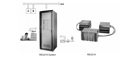
Application The REG216 is intended for the protection of generators and block transformers. The modular hardware and software design allows an extremely flexible installation. Simplicity of adaption to the size of the pri mary system and the desired protection schemes are achieved through the combi nation of a software library and hardware modules. Economic solutions can thus be achieved in the full range of applications for which it is intended. The REG216 software system offers a library of protective functions. Functions suitable for generator and transformer protection are lis ted in the table below. Different degrees of redundancy can be selec ted. Availability and reliability of the protec tion can be chosen to suit the application by duplicating e.g. auxiliary supply units of the whole system. Standard interfaces make REG216 compati ble with different process control systems. Data exchange with higher process control levels are possible, e.g. one-way reporting of digital states and events, measured values and protection parameters. REG216 and REG216 Classic differ with regard to the binary process connection: – REG216 uses the E/A-module 216GD61a. – The REG216 Classic uses the modules 216GE61 / 216GA61 and 216GA62.
Protection functions All protection functions required for the stand-alone protection of generators, power transformers and feeders are available. The system therefore replaces several relays of a conventional protection scheme for such power system equipment. The table on page 2 gives a survey of the most significant protec tion functions. The desired protection functions to suit the particular application can simply be selected from a comprehensive library using the per sonal computer. No knowledge of computer programming is required. All setting ranges are extremely wide to make the protection functions suitable for a multi tude of applications. The following main pa rameters can be set: • Allocation of processing units • Input channel or channels • Pick-up setting • Time delay • Definition of the operating characteristic • Tripping logic • Control signal logic. Setting a corresponding parameter enables the protection functions to be “connected” to particular input channels. Digital input and output signals can also be internally combined logically: • The tripping outputs of each protection function can be assigned to channels of the tripping auxiliary relay assembly in a man ner corresponding to a matrix. • The pick-up and tripping signals can be assigned to the channels of the signalling auxiliary relay assembly. • Provision is available for blocking each protection function with a digital signal (e.g. digital inputs or by using the tripping signal of another protection function). • External signals applied to the digital inputs can be processed in any desired fashion. • Digital signals can be combined to per form logical functions e.g. external en abling or blocking signals with the output signals of an internal protection function and then used to block one of the other protection functions. Remote in- and outputs (RIO580) Using the process bus type MVB, remote in- and output units 500RIO11 can be connected to the REG216 terminals. The input and out put channels can be extended to a large num ber by using the RIO580 remote input/output system. Installing 500RIO11 I/O units close to the process reduces the wiring dramati cally, since they are accessible via fibre optic link from the REG216 terminals. Analog signals can also be connected to the system via the 500AXM11 from the RIO580 family: • DC current 4…20 mA 0…20 mA-20…20 mA • DC voltage 0…10 V-10…10 V • Temp. sensor Pt100. Pt250. Pt1000. Ni100. Ni250. Ni1000
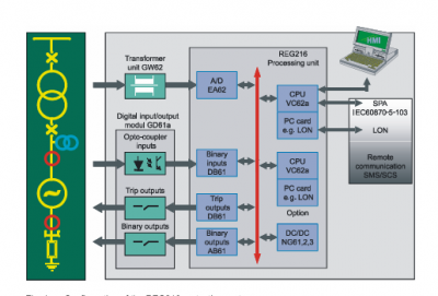
Excellent electromagnetic compatibility has been achieved through careful attention to physical separation of the interfaces from the signal processing units All hardware can be accommodated in one cubicle, which provides a further screen against induced interference and affords physical protection against dust, etc. REG216 has 17 pre-defined rack configura tions with a limited number of I/Os but equipped with the same SW library as the Classic system. Other protection relays for functions which are not part of the REG216 may be installed in the cubicle and correspondingly interwired with REG216. Interfaces to the primary sys tem The following modular assemblies provide interfacing of REG216 to the power system. Input transformer assembly 216GW62 This assembly adjusts the signal levels and provides isolation between the primary sys tem CT and PT circuits and the electronic cir cuits of the protection. One type of PT and two types of CTs are available, to meet differ ent accuracy and dynamic performance requirements. Space is available for up to 12 transformers, which are selected to suit the application. Up to four assemblies can be used, i.e. 48 inputs. Auxiliary relay and optocoupler assembly 216GD61a This assembly is used in the version of REG216. It provides eight tripping relays, each with powerful, potential-free tripping contacts (with surge circuits), 16 auxiliary relays and 16 optocoupler input circuits. Max. four assemblies can be provided. Input auxiliary relay assembly 216GE61 Up to 16 auxiliary relays can be accommo dated, providing complete potential separa tion of digital input signals. Output auxiliary relay assembly 216GA61 Up to 16 auxiliary relays can be accommo dated providing complete potential separation of digital output signals (two contacts per sig nal). Tripping auxiliary relay assembly 216GA62 Up to eight powerful, potential-free tripping contacts and circuits, which provide high speed operation (surge circuit) with reduced consumption after operation (economy cir cuit) are provided. The tripping auxiliary relay assembly can be optionally fitted with a tripping logic diode matrix to enable direct coupling of external signals. REG216 can also read and process external signals via digital inputs.
arrangements in conjunction with the output unit 216DB61and the input auxiliary relay assembly 216GE61 can be provided. Parallel bus and electronic units The electronic units are of plug-in design and accommodated in an equipment rack with the standard dimension 19″, 6U (1U = 44.45 mm). An equipment rack of this kind is di vided into 21 standard divisions. The ex change of data via the parallel bus B448C is controlled and monitored by all units avail able. The protection system is based on a data bus with digital signal processing for most func tions; signal conditioning, analog and digital inputs, A/D conversion, processing and signal output. The components of the system are: • Static plug-in units, which exchange data via a powerful parallel bus • Interfaces to the process (primary system, station equipment), which are isolated from the digital processing unit. Equipment rack 216MB66/216MB68 and parallel bus B448C The main features of the parallel bus B448C are: • Specification based on IEEE P 896 (future bus) • Time multiplexing of addresses and data (16 bit) • Asynchronous data transmission with handshake • Integrity checking of each data exchange. • Up to 32 master units having equal status, actively accessing the bus • Common internal 24 V auxiliary supply for all electronic units; redundant 24 V are possible. Processing unit 216VC62a • 32 bit processor type 80486DX-2 • Application software on Flash EPROM • Operating data on RAM • Settings on non-volatile Flash EPROM • Potential-free RS-423 interface for PC operation • Connection to the station control with transmission of messages • Time clock synchronizing for time-tagging of events • Non-volatile event and disturbance mem ory (gold capacitor buffered) • Space requirement: two rack divisions. Analog Input unit 216EA62 • 24 inputs sampled simultaneously in groups of six • Sampling frequency 600 (720) Hz for a power frequency of 50 (60) Hz • Space requirement: two rack divisions. Digital output unit 216AB61 • 32 outputs for controlling the relays of the output auxiliary relay assembly • Short-circuit proof • Front plate LEDs for indication of acti vated relays • Space requirement: one rack division. Tripping output and binary input unit 216DB61 • 8 outputs for two-pole control of auxiliary tripping relays • Monitored output amplifiers • 16 digital inputs for the signals from the input auxiliary relay assembly (two each can be used to externally enable and block tripping respectively) • Activated outputs and inputs indicated by LEDs • Front space requirements: one rack divi sion. Auxiliary DC supply unit 216NG61. 216NG62 and 216NG63 • Versions for 36 to 312 V DC input • Outputs 24V DC, 150 W • Short-circuit and overload-proof outputs • Parallel connection to increase rating • Parallel connection for redundancy (2 outputs) • Space requirement: 3 rack divisions. All the REG216 protection functions operate with sampled primary system voltages and currents.